
NUC-340 · Lesson 11 of 12 · 20 min
Materials for advanced reactors
Malik's group has been asked to support reviews of several advanced reactor designs that have entered the CNSC's pre-licensing vendor design review, including sodium-cooled and molten salt concepts, as well as the BWRX-300 at Darlington. "The BWRX-300 uses materials we know well," he says. "The others take us somewhere new: temperatures of 500 to 750 degrees, coolants that are liquid metal, molten salt or helium, and fuels that are not uranium dioxide pellets in zirconium. Most of the questions in those reviews are materials questions."
What changes in advanced reactors
Water-cooled reactors operate below about 350 °C because water must stay liquid or boil at a pressure the vessel can contain. Advanced designs use coolants that stay liquid or gaseous at low pressure and high temperature, which allows higher thermal efficiency and process heat for industry. Higher temperatures change the materials problem in three ways. Thermal creep becomes a primary design consideration, not a secondary one. Coolant compatibility becomes different: corrosion in sodium, salt and impure helium follows different rules from corrosion in water. And radiation effects such as void swelling and helium embrittlement, minor in water reactors, become important.
| Reactor type | Coolant and outlet temperature (approximate) | Key structural materials | Main materials concerns |
|---|---|---|---|
| Sodium-cooled fast reactor | sodium, about 500 to 550 °C | 316H stainless, Grade 91 steel; ferritic–martensitic cladding | creep–fatigue, swelling of cladding, sodium compatibility |
| Molten salt reactor | fluoride or chloride salt, about 600 to 700 °C | nickel alloys such as Hastelloy N; 316H stainless | salt corrosion, tellurium embrittlement, creep |
| Fluoride salt-cooled high-temperature reactor | fluoride salt with TRISO fuel, about 600 to 650 °C | 316H stainless; graphite | salt corrosion, graphite behaviour |
| High-temperature gas reactor | helium, about 700 to 750 °C or higher | Alloy 800H, Alloy 617; graphite; TRISO fuel | creep at high temperature, helium impurities, graphite ageing |
| Lead-cooled fast reactor | lead or lead–bismuth, about 480 to 550 °C | ferritic and austenitic steels with oxygen control | liquid metal corrosion and erosion |
| Heat pipe microreactor | sodium or potassium heat pipes, about 600 to 700 °C | stainless steels, refractory alloys | creep, heat pipe compatibility |
Designing against creep
Above about 425 °C for ferritic steels and 450 °C for austenitic steels, the ASME Code requires time-dependent design. ASME Section III, Division 5 sets the rules for high-temperature reactors. Allowable stresses depend on both temperature and design life, because a material that can carry a stress for one year may rupture under the same stress in 30 years. Designers must also evaluate creep–fatigue interaction, since cycles combined with hold periods at temperature damage material faster than either alone, and ratcheting, the progressive build-up of strain under cyclic loading.
Creep rupture data are expensive to obtain because tests run for years. Engineers extrapolate them with time–temperature parameters. The Larson–Miller parameter combines temperature T in kelvin and rupture time t in hours:
where C is a constant, often near 20. Tests at higher temperature and shorter time give the same parameter, and therefore the same stress, as service at lower temperature and longer time. Extrapolation beyond about three times the longest test time is treated with caution.
Division 5 lists a small number of qualified materials, including 304H and 316H stainless steels, Alloy 800H, Grade 91 steel and, more recently, Alloy 617. Designers of advanced reactors in Canada use these rules within the CSA N285 and CNSC framework, together with materials data from international programs.
Worked problem
Which alloy can carry load at 650 °C for 60 years?
Using illustrative Larson–Miller fits of the form allowable stress = a − b × P/1000 for four alloys, compare the allowable stress at 550, 650 and 750 °C for a 60-year life at 90 percent capacity.
Show solution
- Life = 60 × 8766 × 0.9 ≈ 473 000 hours, so log₁₀ t ≈ 5.67.
- At 650 °C, T = 923 K and P/1000 ≈ 923 × 25.67 / 1000 ≈ 23.7 for C = 20.
- Each alloy's fit then gives its allowable stress; the ferritic steel's fit, with C = 30, falls to zero above about 600 °C.
Answer: Grade 91 is useful at sodium reactor temperatures but not at 650 °C; 316H is marginal at 650 °C; Alloy 800H and Alloy 617 can carry load at 650 °C, and only Alloy 617 at 750 °C. These are teaching fits; real design uses Division 5 tables and full creep–fatigue evaluation.
# Materials for advanced reactors: comparing candidate structural materials at
# outlet temperature against a creep-limited allowable stress (illustrative Larson-Miller fits).
import math
def lmp_allowable(T_C, life_h, C, a, b):
    # Larson-Miller parameter P = T(K) (C + log10 t); allowable stress = a - b*P (MPa)
    P = (T_C + 273.15) * (C + math.log10(life_h)) / 1000.0
    return max(0.0, a - b * P)
alloys = {"316H stainless": (20, 1080.0, 45.0), "Alloy 800H": (20, 980.0, 38.0),
          "Grade 91 steel": (30, 1100.0, 34.0), "Alloy 617": (20, 1250.0, 45.0)}
designs = {"sodium fast reactor": 550, "molten salt reactor": 650, "high-temperature gas reactor": 750}
life = 60 * 8766 * 0.9
for d, T in designs.items():
    row = ", ".join(f"{n} " + (f"{v:.0f}" if (v := lmp_allowable(T, life, *p)) > 0 else "not usable") for n, p in alloys.items())
print(f"{d:28s} at {T} C (MPa): {row}")sodium fast reactor at 550 C (MPa): 316H stainless 129, Alloy 800H 177, Grade 91 steel 102, Alloy 617 299 molten salt reactor at 650 C (MPa): 316H stainless 13, Alloy 800H 79, Grade 91 steel not usable, Alloy 617 183 high-temperature gas reactor at 750 C (MPa): 316H stainless not usable, Alloy 800H not usable, Grade 91 steel not usable, Alloy 617 68
Coolant compatibility
Sodium is benign to steels when oxygen is kept very low, a few parts per million: corrosion is slow, and sodium's excellent heat transfer allows thin-walled components. The concerns are carbon transfer between steels, which can carburise or decarburise them, and sodium's violent reaction with water and air, which is a design and safety issue rather than a corrosion one. Molten fluoride salts dissolve the protective oxide films that steels rely on, so corrosion depends on the salt's redox state. Chromium is selectively leached from alloys, leaving voids beneath the surface. Nickel-based alloys with modest chromium, such as Hastelloy N developed for the Molten Salt Reactor Experiment at Oak Ridge in the 1960s, resist this well. Fission product tellurium can also attack grain boundaries in nickel alloys, causing shallow embrittlement, which was found in that experiment and addressed by alloy and redox control.
Helium is chemically inert, but in a real reactor it carries small amounts of water, hydrogen, carbon monoxide and methane. Depending on their balance, these can oxidise, carburise or decarburise high-temperature alloys over decades, changing their creep strength. Helium purification systems keep impurities in a controlled range.
Fuels for advanced reactors
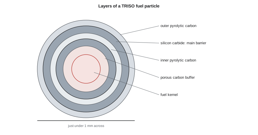
TRISO fuel, used in gas-cooled and salt-cooled designs, consists of uranium oxycarbide or oxide kernels less than a millimetre across, coated with layers of porous carbon, dense pyrolytic carbon and silicon carbide. The silicon carbide layer is a tiny pressure vessel that retains fission products up to about 1600 °C. Thousands of particles are embedded in graphite pebbles or compacts. Qualification programs in the United States have tested TRISO particles to high burnup and through accident-temperature heating tests, showing very low failure fractions.
Sodium fast reactors often use metallic fuel, an alloy of uranium with about 10 percent zirconium, in steel cladding with a sodium bond, or oxide fuel. Metallic fuel swells and releases gas rapidly early in life, which is accommodated by low smeared density and a large gas plenum. A key interaction is fuel–cladding chemical interaction, in which lanthanide fission products diffuse into the cladding and thin it. Cladding materials for high doses are ferritic–martensitic steels such as HT9, which swell far less than austenitic steels.
Materials development
Several new materials are being developed for these demanding conditions. Oxide dispersion strengthened steels contain a fine dispersion of nanometre-scale oxide particles that pin dislocations and trap helium, giving high creep strength and swelling resistance. Silicon carbide composites, described in Lesson 10, are candidates for high-temperature core components. Advanced manufacturing, such as additive manufacturing and powder metallurgy with hot isostatic pressing, is being qualified for nuclear components, which requires showing that the new process gives consistent properties and that codes can accept it. Each new material faces the same hurdle: building enough long-term data, including irradiated data, to support a design life of 60 years.
Irradiation at high temperature
Radiation damage behaves differently at advanced reactor temperatures. At 500 to 700 °C, many of the small defect clusters that harden steels at 300 °C anneal out, so radiation hardening and low-temperature embrittlement are smaller. In their place come mechanisms that need higher temperatures. Void swelling in austenitic steels peaks at roughly 400 to 550 °C, depending on alloy and dose. Helium produced by transmutation collects in bubbles on grain boundaries and, at high temperatures, these bubbles grow under stress and link up, causing high-temperature helium embrittlement: a sharp loss of creep rupture ductility. Irradiation can also change precipitate structures that give high-temperature alloys their creep strength. For fast reactor cores, where doses reach 100 dpa or more, these effects dominate the choice of cladding and duct materials.
| Temperature range (steels) | Dominant radiation effects | Design response |
|---|---|---|
| below about 350 °C | hardening, embrittlement, irradiation creep | toughness margins; surveillance |
| about 400 to 550 °C | void swelling, irradiation creep | swelling-resistant alloys; allowances for growth |
| above about 550 °C | helium embrittlement, thermal creep, phase changes | creep design; low-helium alloys; dose limits |
From data to a licensed design
For a new reactor, the materials case must show that every important component will meet its requirements for its design life in its environment. That requires properties at temperature, including long-term creep and creep–fatigue data; environmental effects of the coolant on those properties; irradiation effects where the component is exposed to neutrons; and an inspection or monitoring plan. Where data are missing, designers can choose a well-characterised material even if it is not optimal, limit the design life of a replaceable component, add surveillance specimens, or design for easy inspection and replacement.
In Canada, a vendor design review by the CNSC is not a licence, but it allows the regulator to identify early whether a design's materials case is likely to meet requirements, and many of the questions raised in such reviews concern high-temperature materials data, coolant chemistry control and in-service inspection.
Supply chains add a practical constraint. Large forgings of high-temperature alloys, nuclear-grade graphite and TRISO fuel are each produced by only a few suppliers worldwide, and each nuclear component must be made under a quality assurance program with full traceability of material heats and test results. A design that relies on an alloy available from only one mill, or on a graphite grade no longer produced, carries a risk that has nothing to do with physics. Materials engineers therefore weigh availability and fabricability alongside properties when they choose materials for new reactors, and they often favour materials already listed in codes and already made at scale, even when a newer material looks better on paper.
Microreactors and transportable designs
Very small reactors, some designed to be transported to remote sites, raise their own materials questions. Many use heat pipes, sealed tubes in which a liquid metal evaporates at the hot end and condenses at the cold end, carrying heat without pumps. The heat pipe wall and wick must be compatible with the working fluid for the life of the core, and the core block, often a metal monolith or graphite, must tolerate steep thermal gradients. Because such reactors may run for years without refuelling and then be returned for decommissioning, the materials must be predictable without frequent inspection. Some designs use high-assay low-enriched uranium, between 5 and 20 percent uranium-235, in TRISO or metallic forms to achieve long core lives in a small volume.
For remote northern communities and mines in Canada, and for military bases and remote sites in the United States, the appeal of these designs is reliable heat and power without long fuel supply chains. The engineering challenge is that a small, sealed, long-lived core must be designed with enough materials margin that it does not need the inspection programs that large plants rely on.
Summary and key terms
- Advanced reactors run at 500 to 750 °C or more in sodium, molten salt, helium or lead, at low pressure.
- Thermal creep, creep–fatigue and coolant compatibility become central design issues.
- ASME Section III, Division 5 sets time-dependent design rules and lists a few qualified high-temperature materials.
- Larson–Miller parameters let short, hot tests stand in for long, cooler service, within limits.
- Molten salts leach chromium; sodium needs low oxygen; helium impurities can oxidise or carburise alloys.
- TRISO particles, metallic fuel and new alloys such as ODS steels each need long qualification programs.
- Time-dependent design
- Design that accounts for creep, using allowable stresses that depend on temperature and life.
- Creep–fatigue interaction
- Damage from cyclic loading combined with hold periods at high temperature.
- Larson–Miller parameter
- A combination of temperature and time used to extrapolate creep rupture data.
- TRISO particle
- A tiny fuel kernel coated with carbon and silicon carbide layers that retain fission products.
- Fuel–cladding chemical interaction
- Diffusion of fission products into cladding, thinning it, in metallic fuel.
- ODS steel
- Oxide dispersion strengthened steel with fine oxide particles for creep and swelling resistance.
Practice problems
Work each problem on paper first, then reveal the answer to check.
Why does creep become a primary design concern in advanced reactors?
Show answer
They operate at 500 to 750 °C, above the temperatures where creep is significant for steels.
What does a Larson–Miller parameter allow engineers to do?
Show answer
Extrapolate long-term creep rupture life from shorter tests at higher temperature.
Why are fluoride salts corrosive to ordinary steels?
Show answer
They dissolve protective oxide films and leach chromium.
What is the role of the silicon carbide layer in a TRISO particle?
Show answer
It acts as a small pressure vessel that retains fission products.
Why are ferritic–martensitic steels used for fast reactor cladding?
Show answer
They swell much less than austenitic steels at high dose.
Lesson quiz · 5 questions
Score 60% or more to complete this lesson.
Create a free account to save your progress, take quizzes and earn a certificate.