
NUC-340 · Lesson 5 of 12 · 20 min
Steels for pressure vessels
Darlington has no large reactor vessel; its pressure boundary inside the core is made of 480 pressure tubes per unit. But the Darlington New Nuclear project's BWRX-300 units will have a single steel vessel, and the steam generators, headers and piping of every CANDU unit are steel. "Steel is the backbone of every nuclear plant," Malik says. "You need to understand why we choose particular steels, how we make them, and what happens to them at welds and under irradiation."
What a reactor vessel must do
A light water reactor vessel holds the core and coolant at about 15.5 MPa and 290 to 325 °C in a PWR, or about 7 MPa and 286 °C in a BWR. It must do this for 60 to 80 years, through hundreds of heat-up and cool-down cycles, with no possibility of practical replacement. It must also tolerate the flaws that are inevitably present in thick welds, which means it must remain tough: able to resist crack growth and fracture even if a flaw exists. The material for such a vessel must be strong, tough, weldable in heavy sections, and available as large forgings or plates of consistent quality.
| Requirement | How it is met |
|---|---|
| Strength at temperature | quenched and tempered low-alloy steel with yield strength of about 350 to 500 MPa |
| Toughness | fine-grained, clean steel; low impurity levels; controlled heat treatment |
| Weldability in thick sections | controlled carbon content, preheat and post-weld heat treatment |
| Corrosion resistance on wetted surfaces | a weld-deposited stainless steel cladding a few millimetres thick on the inner surface |
| Resistance to irradiation embrittlement | low copper, phosphorus and, where practical, nickel in beltline materials |
| Inspectability | designs and surfaces that allow ultrasonic examination of welds |
The steels
North American reactor vessels are made of manganese–molybdenum–nickel low-alloy steels. Early vessels used plates of a grade known as A302B and later A533 Grade B Class 1, rolled to thickness and formed into shells joined by longitudinal and circumferential welds. Later vessels used large ring forgings of A508 Class 3 or similar steels, which remove the longitudinal welds and reduce the length of weld in the high-flux region. Both are typically quenched from about 870 to 900 °C and tempered at about 650 °C to give a tempered bainitic microstructure with a good balance of strength and toughness.
| Element | Typical role |
|---|---|
| Carbon (about 0.2 %) | strength, through carbides; limited for weldability |
| Manganese (about 1.2 to 1.5 %) | hardenability and strength |
| Molybdenum (about 0.5 %) | strength at temperature; resistance to temper embrittlement |
| Nickel (about 0.5 to 1 %) | toughness and hardenability; but raises irradiation sensitivity together with copper |
| Copper | an impurity in older steels and welds; strongly increases irradiation embrittlement |
| Phosphorus and sulphur | impurities kept very low; phosphorus contributes to embrittlement |
Welds are the weak link. Some vessels built in the 1960s and early 1970s were welded with copper-coated wire, which added copper to the weld metal. Copper turned out to be the element most strongly linked to irradiation embrittlement, so these welds now control the embrittlement assessments of the oldest vessels. Modern specifications limit copper and phosphorus tightly in beltline materials.
Design: stress and wall thickness
The hoop stress in a thin cylinder of inner radius R and thickness t under internal pressure P is σ = PR/t. Pressure vessel codes use closely related formulas with allowance for thick-wall effects. A common code-style expression for the required thickness of a cylindrical shell is
where S is the allowable stress and E is the weld joint efficiency. For a PWR vessel with a design pressure of 17.2 MPa and an inner radius of 2.2 m, an allowable stress near 184 MPa gives a required wall of about 220 mm, before the stainless cladding and any corrosion or fabrication allowances. In practice, nuclear vessel design under ASME Section III goes much further, classifying stresses as primary, secondary and peak, and evaluating fatigue for the expected cycles.
Worked problem
Wall thickness and a flaw check
For P = 17.2 MPa and R = 2200 mm with S = 184 MPa and E = 1, find the required thickness. Then estimate the stress intensity for a 25 mm deep surface flaw at the resulting hoop stress, using K_I = 1.1 σ √(πa), and compare it with an upper-shelf toughness of 200 MPa·√m.
Show solution
- t = 17.2 × 2200 / (184 − 0.6 × 17.2) ≈ 218 mm.
- Hoop stress with a 220 mm wall ≈ 17.2 × 2200 / 220 ≈ 172 MPa.
- K_I = 1.1 × 172 × √(π × 0.025) ≈ 53 MPa·√m.
Answer: About 220 mm of wall, and a stress intensity of about 53 MPa·√m, roughly a quarter of the upper-shelf toughness. The margin shrinks greatly if the steel is cold and embrittled, which is why toughness and temperature are tied together in operating limits.
# Steels for pressure vessels: hoop stress, wall thickness and a simple fracture check.
import math
def wall_thickness(P_MPa, R_mm, S_MPa, E=1.0):
    # Thin-shell form t = P R / (S E - 0.6 P), the familiar pressure-vessel code style formula.
    return P_MPa * R_mm / (S_MPa * E - 0.6 * P_MPa)
P, R = 17.2, 2200.0          # design pressure (MPa) and inner radius (mm) of a large PWR vessel
for S in (172.0, 184.0, 200.0):
    print(f"allowable stress {S:5.0f} MPa -> required wall {wall_thickness(P, R, S):5.0f} mm (before cladding and allowances)")
# Linear elastic fracture: K_I = F * sigma * sqrt(pi a) for a surface flaw (F about 1.1)
def K_I(sigma, a_mm, F=1.1):
    return F * sigma * math.sqrt(math.pi * a_mm / 1000.0)
sigma = P * R / 220.0         # hoop stress in a 220 mm wall, MPa
print(f"hoop stress {sigma:.0f} MPa")
for a in (5.0, 10.0, 25.0):
    K = K_I(sigma, a)
print(f"flaw depth {a:4.0f} mm: K_I = {K:5.1f} MPa*m^0.5 vs K_Ic 200 MPa*m^0.5 (upper shelf) -> margin {200/K:4.1f}")allowable stress 172 MPa -> required wall 234 mm (before cladding and allowances) allowable stress 184 MPa -> required wall 218 mm (before cladding and allowances) allowable stress 200 MPa -> required wall 199 mm (before cladding and allowances) hoop stress 172 MPa flaw depth 5 mm: K_I = 23.7 MPa*m^0.5 vs K_Ic 200 MPa*m^0.5 (upper shelf) -> margin 8.4 flaw depth 10 mm: K_I = 33.5 MPa*m^0.5 vs K_Ic 200 MPa*m^0.5 (upper shelf) -> margin 6.0 flaw depth 25 mm: K_I = 53.0 MPa*m^0.5 vs K_Ic 200 MPa*m^0.5 (upper shelf) -> margin 3.8
Fracture toughness and the ductile-to-brittle transition
Ferritic steels such as reactor vessel steels change behaviour with temperature. At high temperatures they fail in a ductile manner, absorbing a great deal of energy as cracks grow by tearing. At low temperatures they fail by cleavage, a brittle mode in which a crack runs across grains with little energy absorbed. Between the two lies a transition region. Charpy impact tests show the transition as an S-shaped curve of absorbed energy against temperature, with a lower shelf, a transition and an upper shelf. Fracture toughness tests show a similar rise of K_Ic or K_Jc with temperature.
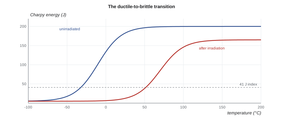
Two parameters summarise the transition for engineering purposes. RT_NDT, the reference temperature for nil-ductility transition, is found from drop-weight and Charpy tests and indexes a lower-bound toughness curve in the ASME Code. More recent practice uses the master curve approach, in which the temperature T₀ at which the median toughness of 25 mm specimens equals 100 MPa·√m locates a statistically based toughness curve. In both cases, the design rule is to keep the vessel warm enough, whenever it is pressurised, that any credible flaw is in tough material.
Welding and residual stresses
Thick welds in vessels and nozzles are made by submerged arc or other processes in many passes. Each pass heats and cools the surrounding metal, leaving a heat-affected zone with a different microstructure and residual stresses that can approach the yield strength. Post-weld heat treatment, holding the whole vessel or a local region at about 600 °C, tempers the heat-affected zone and relieves much of the residual stress. Residual stresses still matter in assessments, because they add to operating stresses at flaws, particularly at dissimilar metal welds between low-alloy steel nozzles and stainless steel piping, where nickel alloy weld metal is often used.
Stainless steel cladding on the inside of the vessel protects the low-alloy steel from corrosion and keeps corrosion products out of the coolant. It is applied by weld overlay. Small cracks under the cladding, called underclad cracks, were found in some vessels and are covered in inspection programs.
Steam generators, piping and nozzles
Other steels in the primary circuit face different challenges. Austenitic stainless steels such as Type 304 and 316 are used for piping, internals and cladding; they are tough at all temperatures and do not have a ductile-to-brittle transition, but they can suffer stress corrosion cracking, as Lesson 8 explains. Cast austenitic stainless steels used for pump casings and some elbows contain ferrite that can embrittle slowly at operating temperature, a process called thermal ageing. Carbon steels are used for secondary piping and, in CANDU reactors, for feeder pipes, where flow-accelerated corrosion is the main concern. Steam generator shells are low-alloy steel, and their tubes are nickel alloys.
In CANDU reactors, the steam generators, the reactor inlet and outlet headers and the feeders are the main steel pressure-boundary components in the primary circuit. Their design follows ASME Section III with the CSA N285 series, and their in-service inspection is governed by CSA N285.4.
Fatigue and design transients
Every heat-up, cool-down, power change and trip cycles the stresses in a vessel and its nozzles. Over decades, these cycles can initiate fatigue cracks at stress concentrations such as nozzle corners and can grow existing flaws. Design under ASME Section III therefore counts the expected design transients, such as heat-ups and cool-downs, reactor trips, loss of load and hydrostatic tests, and calculates a cumulative usage factor by Miner's rule:
where n_i is the number of cycles of type i expected and N_i is the allowable number from the code's design fatigue curve. The curves include large factors on stress and cycles to cover scatter, size and surface effects. Later research showed that light water reactor coolant can shorten fatigue life compared with air, so environmental fatigue correction factors are now applied in licence renewal and new designs. Plants also count actual transients as they occur, so that the remaining usage can be tracked against the design assumption.
| Transient type | Typical design count over 40 or 60 years | Main stressed locations |
|---|---|---|
| Heat-up and cool-down | about 200 | nozzles, flanges, support skirts |
| Reactor trip | several hundred | nozzles and piping connections |
| Loss of load | tens | pressurizer surge line, nozzles |
| Hydrostatic tests | a few | whole pressure boundary |
| Small power changes | thousands | thermal sleeves, mixing tees |
Inspecting thick steel
Thick welds are inspected during fabrication by radiography and ultrasonic testing, and in service by automated ultrasonic examination from the inside of the vessel during refuelling outages, typically on an interval of about ten years under ASME Section XI. Ultrasonic methods can detect and size planar flaws such as lack of fusion or cracks a few millimetres deep. Performance demonstration programs require that procedures, equipment and personnel prove their ability to find and size flaws in realistic test blocks before they are used on a plant. Inspection results feed flaw evaluations: a flaw that is found and sized can be compared with acceptance standards, or analysed with fracture mechanics to show it will not grow to a critical size before the next inspection.
This combination of tough material, conservative design, counting of transients and periodic inspection is sometimes called defence in depth for the pressure boundary. Any one element might have gaps; together they make sudden failure of a well-made vessel extremely unlikely, provided irradiation embrittlement is kept under control. That is the subject of the next lesson.
Summary and key terms
- Reactor vessels must be strong, tough, weldable in thick sections and resistant to irradiation for 60 to 80 years.
- North American vessels use quenched and tempered Mn–Mo–Ni low-alloy steels, as plates or ring forgings, clad inside with stainless steel.
- Copper and phosphorus impurities, especially in older welds, strongly increase irradiation embrittlement.
- Required wall thickness follows from pressure, radius and allowable stress; a PWR vessel wall is about 200 to 250 mm.
- Ferritic steels have a ductile-to-brittle transition, indexed by RT_NDT or the master curve temperature T₀.
- Welds carry residual stresses and heat-affected zones; post-weld heat treatment tempers them and relieves stress.
- Quenched and tempered
- Heat treated by rapid cooling from high temperature, then reheated to improve toughness.
- Beltline
- The region of a reactor vessel opposite the core, which receives the highest neutron fluence.
- RT_NDT
- The reference nil-ductility transition temperature that indexes the ASME toughness curves.
- Master curve
- A statistical description of fracture toughness versus temperature, located by the reference temperature T₀.
- Heat-affected zone
- Base metal next to a weld whose microstructure was changed by welding heat.
- Post-weld heat treatment
- Heating after welding to temper the heat-affected zone and relieve residual stress.
Practice problems
Work each problem on paper first, then reveal the answer to check.
Why is a stainless steel cladding applied inside a low-alloy steel vessel?
Show answer
To protect it from corrosion and keep corrosion products out of the coolant.
Which impurity element most strongly increases irradiation embrittlement of vessel steels?
Show answer
Copper.
Estimate the hoop stress in a 220 mm wall with P = 15.5 MPa and R = 2.2 m.
Show answer
\(15.5 \times 2200/220 = 155\) MPa.
What is the advantage of ring forgings over rolled plates for vessels?
Show answer
They eliminate longitudinal welds and reduce weld length in the beltline.
Why do austenitic stainless steels not need a ductile-to-brittle transition assessment?
Show answer
Their face-centred cubic structure does not show a cleavage transition.
Lesson quiz · 5 questions
Score 60% or more to complete this lesson.
Create a free account to save your progress, take quizzes and earn a certificate.