
NUC-340 · Lesson 6 of 12 · 20 min
Irradiation embrittlement
Hana breaks her first irradiated Charpy specimens in the hot cell, working the remote tongs while a technician watches. The specimens come from a test program on vessel steels for the BWRX-300, and each one shatters with a crisp crack at temperatures where the unirradiated steel bent and tore. "That is the whole story of this lesson," Malik says. "Same steel, same temperature, less energy. The neutrons have moved the transition up the temperature scale. For a CANDU unit the equivalent question is the toughness of the pressure tubes; for a vessel reactor it is the beltline."
What embrittlement is
Irradiation embrittlement is the loss of fracture toughness caused by neutron irradiation. In ferritic steels it appears in two ways. The ductile-to-brittle transition shifts to higher temperatures, so the steel is brittle over a wider range of temperatures. And the upper-shelf energy, the energy absorbed in fully ductile fracture, falls. Both effects come from radiation hardening: the small solute clusters and defect clusters of Lesson 2 raise the yield strength, making it easier for cleavage to start before plastic deformation can blunt a crack.
The shift is conventionally measured by the change in the Charpy temperature at which the absorbed energy reaches 41 J (30 ft·lb), denoted ΔT₄₁J or ΔT30. It is added to the initial reference temperature to give an adjusted reference temperature (ART) that indexes the toughness curves used in operating limits:
What controls the shift
| Variable | Effect on the shift | Reason |
|---|---|---|
| Fast fluence | rises with fluence, but less than proportionally | damage accumulates while some features saturate |
| Copper content | strong increase above about 0.05 to 0.1 wt% | copper-rich clusters form rapidly under irradiation |
| Nickel content | increases the effect of copper; matters alone at high fluence | Mn–Ni–Si clusters form, especially late in life |
| Phosphorus | increases the shift | segregation and hardening |
| Irradiation temperature | lower temperature gives a larger shift | less thermal recovery of defects |
| Flux (dose rate) | at the same fluence, lower flux can give a larger shift in some steels | more time for diffusion-controlled clustering |
Copper is the dominant chemistry variable in older materials. Under irradiation, copper atoms, which are supersaturated in the steel, cluster within a few years into nanometre-sized copper-rich precipitates that strongly harden the steel. Once the copper is used up, the copper contribution saturates. Nickel, manganese and silicon also cluster, more slowly, so at the high fluences reached in long-term operation these late-blooming phases can add to the shift even in low-copper steels. This is why extending operation to 80 years requires trend models validated at high fluence.
Trend curves
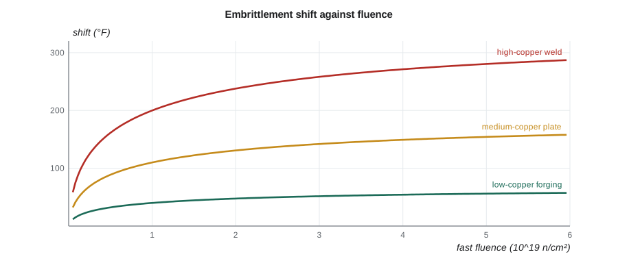
Embrittlement trend curves predict the shift from chemistry and fluence. A widely taught form, used for decades in the United States in NRC Regulatory Guide 1.99 Revision 2, writes the shift as a chemistry factor CF times a fluence function. Canadian designers of vessel reactors, such as the BWRX-300, use comparable correlations through the ASME Code and international data.
Here f is the fast fluence (E > 1 MeV) at the depth of interest in units of 10¹⁹ n/cm². The exponent itself falls as fluence rises, which gives the curve its flattening shape. The chemistry factor ranges from a few tens of degrees Fahrenheit for clean modern steels to over 200 °F for high-copper welds. Fluence is attenuated through the vessel wall, so the shift is greatest at the inner surface and smaller at a quarter of the wall thickness, the location usually used for heat-up and cool-down limits.
Worked problem
Adjusted reference temperature of a high-copper weld
A beltline weld has an initial RT_NDT of 0 °F and a chemistry factor of 200 °F. At a fluence of 2 × 10¹⁹ n/cm², with a margin of 56 °F, find the shift and the adjusted reference temperature.
Show solution
- Fluence factor: f = 2, so the exponent is 0.28 − 0.10 log₁₀ 2 = 0.250, and 2^0.250 ≈ 1.19.
- Shift = 200 × 1.19 ≈ 238 °F.
- Adjusted reference temperature = 0 + 238 + 56 ≈ 294 °F.
Answer: About 294 °F (about 146 °C). The weld's transition has moved far above room temperature, which constrains how the vessel may be heated up, cooled down and pressurised.
# Irradiation embrittlement: a shift in the reference temperature with fluence,
# using the form of the long-used US trend curve: shift = CF * f^(0.28 - 0.10 log10 f)
# where f is the fast fluence in units of 1e19 n/cm2 (E > 1 MeV). The chemistry factor
# (CF) depends on copper and nickel; the CF values below are illustrative.
import math
def fluence_factor(f19):
    return f19 ** (0.28 - 0.10 * math.log10(f19))
materials = {"weld, high copper": 200.0, "plate, medium copper": 110.0, "modern low-copper forging": 40.0}   # F
RT_initial = 0.0          # F
for f19 in (0.5, 1.0, 2.0, 4.0, 6.0):
    row = []
    for name, CF in materials.items():
        shift = CF * fluence_factor(f19)
        row.append(f"{name} {shift:5.0f} F")
    print(f"fluence {f19:3.1f}e19: " + "; ".join(row))
# Compare with a screening-type limit of 270 F for plates and axial welds (illustrative check)
CF, margin = 200.0, 56.0
for f19 in (1.0, 2.0, 3.0, 4.0):
    RT = RT_initial + CF * fluence_factor(f19) + margin
print(f"high-copper weld at {f19:.0f}e19: adjusted reference temperature {RT:5.0f} F -> {'below' if RT < 270 else 'above'} 270 F")fluence 0.5e19: weld, high copper 161 F; plate, medium copper 89 F; modern low-copper forging 32 F fluence 1.0e19: weld, high copper 200 F; plate, medium copper 110 F; modern low-copper forging 40 F fluence 2.0e19: weld, high copper 238 F; plate, medium copper 131 F; modern low-copper forging 48 F fluence 4.0e19: weld, high copper 271 F; plate, medium copper 149 F; modern low-copper forging 54 F fluence 6.0e19: weld, high copper 287 F; plate, medium copper 158 F; modern low-copper forging 57 F high-copper weld at 1e19: adjusted reference temperature 256 F -> below 270 F high-copper weld at 2e19: adjusted reference temperature 294 F -> above 270 F high-copper weld at 3e19: adjusted reference temperature 314 F -> above 270 F high-copper weld at 4e19: adjusted reference temperature 327 F -> above 270 F
Pressure-temperature limits
Embrittlement matters in operation because the vessel is pressurised when it is cold, during start-up and shutdown. Operating limits under Appendix G of the ASME Code, and in the United States 10 CFR 50 Appendix G, define allowable pressure as a function of coolant temperature so that the stress intensity at a postulated reference flaw, a quarter of the wall deep, stays below the lower-bound toughness with a safety factor. As the vessel embrittles, these pressure-temperature curves move to higher temperatures, narrowing the window in which operators can heat up and pressurise. Low-temperature overpressure protection systems guard against accidental pressurisation of a cold vessel.
Pressurized thermal shock
The most severe challenge to an embrittled vessel is pressurized thermal shock (PTS). If cold emergency coolant is injected while the system remains at or is repressurised to high pressure, the inner surface of the vessel cools rapidly. Thermal stresses then add to pressure stresses at the inner surface, exactly where the steel is most embrittled. If a flaw were present there, the combination could, in principle, cause it to extend.
In the United States, 10 CFR 50.61 sets screening criteria for the reference temperature for PTS: 270 °F for plates, forgings and axial welds and 300 °F for circumferential welds, evaluated at the end of the licence. For vessel reactors built in Canada, such as the BWRX-300, PTS and brittle fracture are addressed in the design and safety analysis under CNSC requirements and ASME Code rules. For CANDU units, the analogous concern is the fracture toughness of pressure tubes at low temperature with high hydrogen content, managed through CSA N285.8 and limits on heat-up and cool-down.
Fluence reduction is the main practical remedy. Low-leakage core loading patterns place used fuel at the core periphery, reducing the flux at the vessel wall by a substantial fraction. Some plants have also placed dummy assemblies or absorbers at the corners closest to critical welds.
Upper-shelf energy and toughness
The second effect of irradiation, the drop in Charpy upper-shelf energy, matters because a vessel at operating temperature is in the upper-shelf region, where fracture is ductile. If the upper-shelf energy falls too low, ductile tearing could occur at loads lower than intended. U.S. rules require the upper-shelf energy to remain above 68 J (50 ft·lb) throughout the licence, unless an equivalent margins analysis shows adequate protection. Surveillance data on upper-shelf drop are predicted with their own correlations.
Surveillance programs
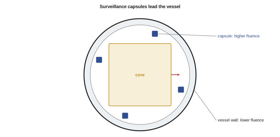
Because embrittlement depends on so many variables, predictions are anchored to the plant's own materials. Surveillance capsules contain Charpy, tensile and sometimes fracture toughness specimens of the beltline plate or forging and weld, plus dosimeters to measure the fluence they receive. They sit closer to the core than the vessel wall, so their fluence leads that of the vessel by a lead factor, and withdrawing them in turn gives advance warning. The measured shifts are compared with the trend curve; if they are consistently higher, plant-specific adjustments are made. Data from many plants are pooled to refine the correlations.
After the specimens are broken, Malik shows Hana how to fit the S-shaped Charpy curve and read off the 41 J temperature. The shift from the baseline curve is a little smaller than the trend curve predicted, which he says is good news but not a reason to relax: one capsule is one data point.
Measuring toughness directly
Charpy shifts are an indirect measure of toughness; the code curves translate them into fracture toughness through correlations. A more direct approach is to test small fracture toughness specimens, such as precracked Charpy-size bars or compact tension specimens, that can fit inside surveillance capsules. The master curve method, standardised in ASTM E1921, makes this practical. It recognises that cleavage toughness in the transition region scatters widely because cleavage starts at a weakest link near the crack tip, and it describes that scatter with a Weibull distribution of fixed shape. Testing six or more small specimens gives the reference temperature T₀, and the curve then gives the median toughness and tolerance bounds at any temperature in the transition. The ASME Code allows a reference temperature RT_T0, based on T₀, to be used in place of RT_NDT.
Direct toughness data reduce the reliance on Charpy correlations and their large margins. They also allow toughness to be measured on reconstituted specimens, where the broken halves of earlier Charpy specimens are welded to new end tabs, giving more data from the same irradiated material.
Embrittlement beyond the vessel
Embrittlement is not only a vessel issue. Austenitic stainless steels in core internals do not have a ductile-to-brittle transition, but at high doses they lose much of their ductility and fracture toughness, and their resistance to stress corrosion cracking falls, as Lesson 8 explains. Cast austenitic stainless steels embrittle thermally at operating temperature over decades. Zirconium alloy pressure tubes lose fracture toughness with fluence and with hydrogen content, particularly at low temperatures. BWR vessels have lower fluence than PWR vessels because their core is surrounded by a thicker water annulus, but their beltline welds still need surveillance.
| Material | Form of embrittlement | Main control |
|---|---|---|
| Vessel steels | transition shift and upper-shelf drop | surveillance, trend curves, P–T limits, PTS screening |
| Zr–2.5 % Nb pressure tubes | toughness falls with fluence and hydrogen, especially when cold | removed-tube tests, hydrogen limits, heat-up limits |
| Stainless steel internals | loss of ductility and toughness at high dose | inspection, bolt replacement, evaluation programs |
| Cast stainless steel | thermal ageing of ferrite | screening by ferrite content and casting method |
The common thread is that toughness is a property that changes with time, and safety depends on knowing its current value and how fast it is changing. Ageing management programs, discussed in Lesson 12, bring these monitoring activities together.
Summary and key terms
- Irradiation embrittlement raises the ductile-to-brittle transition temperature and lowers the upper-shelf energy of ferritic steels.
- The shift rises with fluence and copper, nickel and phosphorus content, and is larger at lower irradiation temperatures.
- Trend curves express the shift as a chemistry factor times a fluence function; the adjusted reference temperature adds a margin.
- Pressure-temperature limits keep a cold vessel from being pressurised beyond what its toughness allows.
- Pressurized thermal shock combines cold injection with pressure; screening criteria and fluence reduction manage it.
- Surveillance capsules, with a lead factor, show in advance how the vessel will embrittle.
- Adjusted reference temperature
- The initial RT_NDT plus the irradiation shift plus a margin.
- Chemistry factor
- A trend-curve coefficient that depends on copper and nickel content.
- Pressurized thermal shock
- A transient in which cold injection cools the vessel wall while pressure stays high.
- Upper-shelf energy
- The Charpy energy absorbed in fully ductile fracture.
- Lead factor
- The ratio of capsule fluence to vessel fluence at the point of interest.
- Low-leakage core
- A loading pattern that places used fuel at the periphery to reduce vessel fluence.
Practice problems
Work each problem on paper first, then reveal the answer to check.
What two changes does irradiation cause in the Charpy curve of a vessel steel?
Show answer
It shifts the transition to higher temperatures and lowers the upper-shelf energy.
Which element produces rapid early embrittlement in older welds?
Show answer
Copper.
Why are heat-up and cool-down limits more restrictive late in life?
Show answer
The vessel is more embrittled, so it must be warmer before it can be pressurised.
Give one way of reducing the fluence at a critical weld.
Show answer
A low-leakage core loading pattern or absorbers at the nearest core positions.
What does the lead factor of a surveillance capsule mean?
Show answer
Its fluence is higher than the vessel's, so it shows future embrittlement in advance.
Lesson quiz · 5 questions
Score 60% or more to complete this lesson.
Create a free account to save your progress, take quizzes and earn a certificate.