
LVT-340 · Lesson 7 of 12 · 18 min
Fibre optics review
Maya is sitting the copper exam, not the fibre one, but every BICSI installer exam includes fibre questions, and the Technician exam has a full fibre section. Teo's Installer 1 exam has fibre basics too. Fibre questions are good marks for prepared candidates because the facts are few, precise and stable: a handful of fibre types, wavelengths, connector names, loss allowances and test methods. This review covers LVT-210, with LVT-120 lesson 8 for fibre's place in the cabling model.
Safety first
LVT-210 lesson 3 covered fibre safety, and exams always include it. Never look into the end of a fibre or a connector, with or without magnification, unless the source is known to be off and disconnected; the light used in telecommunications is invisible and can damage the eye. Use an optical power meter, not your eye, to check for light. Collect cleaved fibre ends in a marked container, never on the floor or the bench where they can enter skin. Wear safety glasses when cleaving and splicing. Do not eat or drink where fibre is being prepared. Use cleaning solvents with ventilation and away from ignition sources, and dispose of solvent-soaked wipes properly.
Exam trap: a visual fault locator emits visible red light and is used to find breaks and trace fibres, but it is still a laser and should not be looked into directly. A question asking whether visible light is safe to look at is testing this.
Fibre types
| Type | Core | Usual jacket colour | Wavelengths | Typical use |
|---|---|---|---|---|
| OM1 | 62.5 µm multimode | Orange | 850 and 1300 nm | Older installations |
| OM2 | 50 µm multimode | Orange | 850 and 1300 nm | Older installations |
| OM3 | 50 µm laser-optimized | Aqua | 850 nm (and 1300) | 10G and faster over short reach |
| OM4 | 50 µm laser-optimized | Aqua or violet | 850 nm (and 1300) | Longer reach than OM3 |
| OM5 | 50 µm wideband | Lime green | 850 to 953 nm | Wavelength multiplexing on multimode |
| OS2 | About 9 µm singlemode | Yellow | 1310 and 1550 nm | Backbones, campus, long reach |
Multimode fibre has a large core and is used with low-cost light sources over distances up to a few hundred metres; its reach is limited by modal dispersion, which depends on the fibre's bandwidth grade. Singlemode fibre has a small core, carries one mode and reaches kilometres; its cost is mainly in the transceivers. Common reach figures for 10 Gb/s short-wavelength links are about 300 m on OM3 and 400 m on OM4; parallel optics at 40 and 100 Gb/s reach about 100 m on OM3 and 150 m on OM4.
Exam trap: never mix multimode core sizes in one link. Connecting 62.5 µm fibre to 50 µm fibre loses a large share of the light at the joint in one direction, and the loss depends on direction, so a test in one direction may pass while the other fails.
Connectors and polarity
LVT-210 lesson 6 covered connectors. LC is the common small connector for duplex links; SC is larger and still common; MPO carries 8, 12, 16 or 24 fibres in one ferrule for high-density and parallel links. Polish matters: UPC connectors have a flat-domed end face with low reflectance; APC connectors are polished at an angle, usually 8 degrees, for very low reflectance, and their housings are green. An APC connector must never be mated with a UPC connector; the gap between the end faces causes high loss and can damage them.
Polarity means that the transmitter at one end connects to the receiver at the other. Duplex links use A-to-B polarity, in which each fibre goes from position A at one end to position B at the other. MPO systems use one of the methods defined in TIA-568.3, such as Methods A, B and C, which differ in trunk type and how the polarity flip is made; mixing components from different methods in one channel is the usual cause of an MPO link with no light.
Splicing and termination
LVT-210 lessons 7 and 8 covered the methods. Fusion splicing welds two fibres with an electric arc and gives the lowest loss, typically well under 0.1 dB with a good cleave; the standard's allowance for a splice is 0.3 dB. Mechanical splices hold fibres in alignment with gel and give higher loss. Field termination can use pre-terminated cable, factory-polished pigtails fusion spliced to the cable, splice-on connectors, or mechanical connectors. The splicer's loss estimate is only an estimate; the link test is the measurement.
Exam trap: the cleave decides the splice. A question asking for the most common cause of high splice loss is looking for a poor cleave, such as a chipped or angled end, or dirt on the fibre, not the splicer's arc settings.
Cleaning and inspection
Dirty connectors are the most common cause of fibre problems. The rule from LVT-210 lesson 9 is inspect before you connect: look at every end face with a fibre microscope or probe before mating, clean it if needed and inspect again. End-face acceptance is set by IEC 61300-3-35, which divides the end face into zones and sets limits on scratches and defects in each; the core zone has the strictest limits. Dry cleaning with a lint-free wipe or a click cleaner is tried first; wet-to-dry cleaning with an approved solvent is used for stubborn contamination. Dust caps protect but do not clean, and an unused cap can itself be dirty.
Loss budgets and Tier 1 testing
LVT-210 lesson 10 built loss budgets from the TIA-568.3 allowances. A budget adds the allowed loss of every element in the link.
| Element | TIA-568.3 allowance |
|---|---|
| Mated connector pair | 0.75 dB |
| Splice | 0.3 dB |
| Multimode fibre at 850 nm | 3.5 dB per km |
| Multimode fibre at 1300 nm | 1.5 dB per km |
| Singlemode fibre, inside plant | 1.0 dB per km |
| Singlemode fibre, outside plant | 0.5 dB per km |
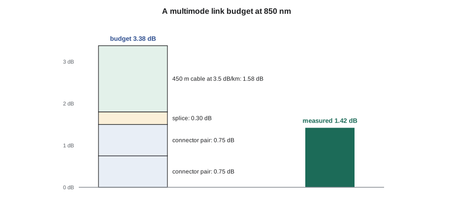
Tier 1 testing measures the loss of each fibre with a light source and power meter, called an optical loss test set, at the wavelengths the standard requires: 850 and 1300 nm for multimode and 1310 and 1550 nm for singlemode. The result must be no more than the budget. The reference must be set by the method the standard specifies, commonly the one-cord method, so that the measured loss includes both end connections. Multimode testing uses an encircled flux compliant launch so that results are repeatable.
Worked problem
A budget for a backbone fibre
A singlemode inside-plant backbone fibre is 320 m long with a connector pair at each end and one fusion splice. What is its loss budget at 1310 nm, and does a measured loss of 1.05 dB pass?
Show solution
- Connectors: 2 × 0.75 = 1.50 dB.
- Splice: 1 × 0.3 = 0.30 dB.
- Fibre: 0.320 km × 1.0 dB per km = 0.32 dB.
- Budget: 1.50 + 0.30 + 0.32 = 2.12 dB; 1.05 dB is well within it.
Answer: The budget is 2.12 dB and the link passes. The common errors are using the outside plant figure of 0.5 dB per km for an inside link, or counting one connector instead of a connector pair at each end.
# Fibre link loss budgets (TIA-568.3 allowances) compared with measured Tier 1 results
CONN, SPLICE = 0.75, 0.30
ATTEN = {("MM", 850): 3.5, ("MM", 1300): 1.5, ("SM-in", 1310): 1.0, ("SM-in", 1550): 1.0,
         ("SM-out", 1310): 0.5, ("SM-out", 1550): 0.5}

def budget(kind, nm, metres, pairs, splices):
    return pairs * CONN + splices * SPLICE + metres / 1000 * ATTEN[(kind, nm)]

links = [  # (name, kind, wavelength, length m, connector pairs, splices, measured dB)
    ("Riser fibre 3", "MM", 850, 450, 2, 1, 1.42),
    ("Riser fibre 3", "MM", 1300, 450, 2, 1, 1.05),
    ("Backbone 7", "SM-in", 1310, 320, 2, 1, 1.05),
    ("Campus 12", "SM-out", 1550, 1850, 2, 2, 2.95),
    ("Campus 14", "SM-out", 1550, 1850, 2, 2, -0.12),
]
for name, kind, nm, m, c, s, meas in links:
    b = budget(kind, nm, m, c, s)
    if meas < 0:
        verdict = "CHECK REFERENCE (negative loss)"
    elif meas <= b:
        verdict = f"PASS, margin {b - meas:.2f} dB"
    else:
        verdict = f"FAIL by {meas - b:.2f} dB"
print(f"{name:14s} {nm:4d} nm budget {b:4.2f} dB measured {meas:5.2f} dB {verdict}")Riser fibre 3 850 nm budget 3.38 dB measured 1.42 dB PASS, margin 1.96 dB Riser fibre 3 1300 nm budget 2.48 dB measured 1.05 dB PASS, margin 1.43 dB Backbone 7 1310 nm budget 2.12 dB measured 1.05 dB PASS, margin 1.07 dB Campus 12 1550 nm budget 3.03 dB measured 2.95 dB PASS, margin 0.08 dB Campus 14 1550 nm budget 3.03 dB measured -0.12 dB CHECK REFERENCE (negative loss)
The code calculates budgets for a few typical links and compares them with measured results, the way a Tier 1 report does. Two of the results teach more than the passes. Campus 12 passes by only 0.08 dB; it meets the standard, but a link that close to its budget on day one has no room for a dirty connector later, so a good technician cleans, inspects and retests it, and looks at its OTDR trace for a bend or a poor splice before signing it off. Campus 14 shows a negative loss, which is physically impossible for a passive link: it means the reference was set with a dirty or poorly seated cord, or the reference cords were changed after the reference was taken. The fix is to reset the reference properly and retest every fibre measured since the last good reference.
Tier 2 testing with an OTDR
An optical time domain reflectometer, covered in LVT-210 lesson 11, sends pulses into the fibre and measures the light scattered and reflected back. Its trace shows distance along the fibre and the loss and reflectance of each event: connectors, splices, bends and the far end. Launch and receive cables, typically a few hundred metres for multimode and longer for singlemode, are needed so that the first and last connectors can be measured, because the OTDR cannot see events in its dead zone right after the pulse. Splice loss is measured from both directions and averaged, because a splice between fibres with slightly different backscatter can appear as a gain in one direction, called a gainer.
Exam trap: an OTDR does not replace Tier 1 loss testing. Tier 2 is an addition that shows where losses occur; the standard's acceptance test is still the loss measurement with a source and power meter.
Fibre installation reminders
LVT-210 lessons 4 and 5 covered installation, and a few rules appear often. Fibre cable has a pulling tension limit set by the manufacturer for each cable, much higher for outside plant cable with strength members than for indoor distribution cable, and the pulling grip attaches to the strength members, not to the jacket or the fibres. The minimum bend radius is commonly 20 times the cable diameter during pulling, under load, and 10 times when installed with no load, unless the maker gives other figures. Fibre in shared pathways is often protected in innerduct, which must have the same fire rating as the space it passes through. Slack is stored in enclosures or in loops at both ends so that the cable can be re-terminated or relocated, with the loops kept above the minimum bend radius.
Exam trap: a pull that exceeds the tension limit may not show any damage in a test the same day. Stressed fibres can crack later, which is why the limit is never exceeded and a breakaway swivel or a tension meter is used on long pulls.
Reading a Tier 1 result
A Tier 1 report lists each fibre with its length, loss at each wavelength, the limit and the margin. Reading it well means checking more than the pass or fail column. All fibres in a cable should show similar losses; one fibre much higher than its neighbours points to a dirty or damaged connector on that fibre, even if it passes. Multimode loss at 1300 nm is normally lower than at 850 nm, because the fibre's attenuation is lower at the longer wavelength; a result where 1300 nm is higher than 850 nm suggests a bend or a stressed section, which affects the longer wavelength more. And the lengths should match the cable route; a length far from the expected value means the fibre was not where the label said.
Common mistakes
MistakeLooking into a connector to see whether it is lit.
InsteadUse a power meter; never look into a fibre.
MistakeMating an APC connector with a UPC connector.
InsteadMatch polishes; APC housings are green.
MistakeMixing 62.5 µm and 50 µm multimode.
InsteadUse one core size throughout a link.
MistakeConnecting without inspecting.
InsteadInspect before you connect, clean if needed and inspect again.
MistakeUsing the outside plant attenuation for an inside link.
InsteadUse 1.0 dB per km for inside plant singlemode.
MistakeTreating OTDR results as the acceptance test.
InsteadTier 1 loss testing is required; Tier 2 adds detail.
Summary and key terms
- Never look into a fibre; use a power meter; collect fibre ends in a marked container.
- Know OM1 to OM5 and OS2: core sizes, jacket colours, wavelengths and typical reach.
- LC, SC and MPO connectors; UPC and APC polishes must not be mixed; polarity connects transmit to receive.
- Allowances: 0.75 dB per connector pair, 0.3 dB per splice, 3.5 and 1.5 dB per km multimode, 1.0 and 0.5 dB per km singlemode.
- Tier 1 loss testing at two wavelengths with the right reference is the acceptance test; Tier 2 OTDR traces locate events.
- Inspect before you connect.
- Encircled flux
- A launch condition for multimode testing that makes loss results repeatable.
- APC
- Angled physical contact polish, usually 8 degrees, with very low reflectance.
- Dead zone
- The distance after a strong reflection in which an OTDR cannot measure events.
- Gainer
- A splice that appears to add light when measured from one direction.
- Optical loss test set
- A light source and power meter used for Tier 1 loss testing.
Practice problems
Work each problem on paper first, then reveal the answer to check.
What colour is an APC connector housing usually?
Show answer
Green.
What is the loss allowance for a mated connector pair?
Show answer
0.75 dB.
At which wavelengths is multimode fibre tested?
Show answer
850 and 1300 nm.
Why are launch cables used with an OTDR?
Show answer
So that the first connector is outside the dead zone and can be measured.
Lesson quiz · 5 questions
Score 60% or more to complete this lesson.
Create a free account to save your progress, take quizzes and earn a certificate.