
IRW-130 · Lesson 3 of 12 · 26 min
Reading placing drawings and bar lists
▶ Video coming soon A video version of this lesson is on the way.
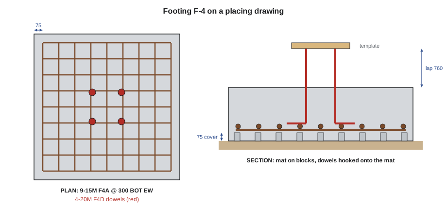
On Monday, October 19, Tobias spread a roll of drawings across two tables in the yard office. They were the placing drawings for the Ashcroft Medical Building foundations, which his gang had placed in June and July, before Shay joined Crossbeam. Beside them was a stack of bar lists stapled into a book. "Every footing you walked past in September is on these sheets," he said. "I want you to find footing F-4, tell me what is in it, find those bars on the list and tell me what they weighed." Shay found the footing in about two minutes. Finding the bars on the list, and understanding why there were two different lengths of the same size bar in one footing, took most of the evening.
This lesson explains the drawings a rod gang works from, how a callout is read, how bars are counted from a spacing, and how the bar list connects the drawing to the bundles on the truck.
Three sets of drawings
Three different sets of drawings describe the reinforcing in a building, and each has a different author and purpose.
- The structural drawings are prepared by the engineer of record. They show the concrete members, their sizes and the reinforcing in each, often in typical details and schedules: a footing schedule, a column schedule, a beam schedule, typical wall details and general notes on cover, laps, hooks and grades. They are the design.
- The placing drawings, sometimes called shop drawings or detailing drawings, are prepared by the reinforcing detailer, usually working for the fabricator. They break the design into individual bars, each with a bar mark, a size, a quantity, a length and a shape, and they show where each one goes. The engineer reviews them before fabrication. They are what the rod gang places from.
- The bar lists, also called bending schedules, list every bar on the placing drawings by mark with its size, count, length and bending dimensions. The fabricator cuts and bends from the list, and each bundle tag carries a bar mark from it.
On the Ashcroft job, the placing drawings and bar lists came from Northbar Reinforcing, the fabricator, where the detailer was Ashok Menon. The engineer's reviewer, Leona Fitzgerald of Fenwick Structural, checked them against the design and returned them stamped "reviewed" with two comments. Tobias's rule is simple: the gang places from the latest reviewed placing drawings and never from an unreviewed set, and if the placing drawing and the structural drawing disagree, the gang stops and asks.
Reading a callout
A callout is the short line of text that tells the placer what bars go in an area. On Canadian drawings, a common form is the quantity, the size, the bar mark and the spacing, for example 9-15M F4A @ 300 BOT EW, meaning nine 15M bars, bar mark F4A, at 300 mm centres, in the bottom, each way. Every detailer has a house style, and the legend on the first placing drawing explains it.
| Abbreviation | Meaning |
|---|---|
| T or TOP | Top layer |
| B or BOT | Bottom layer |
| T&B | Top and bottom |
| EW | Each way: the same bars in both directions |
| EF | Each face (of a wall) |
| IF, OF | Inside face, outside face |
| CONT | Continuous: lapped to run the full length |
| @ | At, followed by the spacing centre to centre |
| TYP | Typical: applies to all similar locations |
| ALT | Alternate: every other bar is different |
| DWL | Dowel |
| STIRR, TIES | Stirrups, ties |
| STD HK | Standard hook |
| SIM | Similar |
Bar marks tell the placer which bundle a bar comes from. Detailers build them from the member and a sequence, so F4A might be the first bar type in footing F-4 and W12C the third bar type in wall W-12. Bent bars often carry a letter or number for their shape. When the tag on the bundle and the mark on the drawing match, the bar is going to the right place.
Counting bars from a spacing
Placing drawings sometimes give the quantity in the callout and sometimes give only a spacing and leave the count to the placer, especially for typical details. Counting bars from a spacing is one of the most common calculations in the trade, and one of the easiest to get wrong by one bar.
The rule is to find the distance the bars must cover, divide by the spacing, round up to the next whole number of spaces, and add one bar, because a row of bars always has one more bar than spaces. The distance to cover is normally the dimension of the member less the cover at each end, measured to the centre of the end bars or, in practice, the length between the first and last bar.
Worked problem
Bars in a footing
Footing F-4 is 2.4 m square. The bottom mat is 15M @ 300 each way, with 75 mm cover to the sides. How many bars are in each direction, and how long is each bar if they are straight?
Show solution
- Distance to cover = 2,400 − 2 × 75 = 2,250 mm.
- Spaces = 2,250 ÷ 300 = 7.5, rounded up to 8.
- Bars = 8 + 1 = 9 in each direction; the actual spacing is 2,250 ÷ 8 ≈ 281 mm, no more than the 300 mm allowed.
- Bar length = 2,400 − 2 × 75 = 2,250 mm = 2.25 m.
Answer: Nine bars each way, 18 bars in all, each 2.25 m long. The spacing on the drawing is a maximum; rounding the spaces down would put the bars too far apart.
If the count on the drawing and the count from the spacing do not agree, the drawing count is usually right, because the detailer may have allowed for a dowel, a pipe or a different end cover that the placer has not noticed. Either way, the difference is a question for the foreperson, not a reason to add or drop a bar.
Reading the bar list
The bar list is a table, and each line is one bar mark. The columns vary by fabricator, but most lists show the same things: the bar mark, the size, the grade, the number of pieces, the total length of each piece, the shape type and the bending dimensions that define the shape, often called A, B, C and so on, and the total weight of that mark.
| Mark | Size | Qty | Length | Shape | A | B | Mass (kg) |
|---|---|---|---|---|---|---|---|
| F4A | 15M | 18 | 2 250 | straight | 63.6 | ||
| F4D | 20M | 4 | 1 520 | 90° hook | 1 253 | 300 | 14.3 |
| P4A | 20M | 6 | 2 900 | straight | 41.0 | ||
| P4T | 10M | 7 | 2 080 | tie | 480 | 480 | 11.4 |
The RSIC Manual of Standard Practice, published by the Reinforcing Steel Institute of Canada, sets out the standard bar shapes, the way bending dimensions are measured and the conventions most Canadian detailers and fabricators use. Dimensions on a bar list are normally out-to-out: measured to the outside of the bar at each bend. The total length shown is the length of bar the fabricator cuts before bending, which the detailer works out from the dimensions; it is not simply the sum of A and B, because the bar follows a curve at each bend.
Worked problem
Checking a mark's weight
Bar mark F4A is 18 pieces of 15M, 2,250 mm long. Check the mass on the list.
Show solution
- Total length = 18 × 2.25 = 40.5 m.
- Mass = 40.5 × 1.570 = 63.6 kg.
Answer: 63.6 kg, matching the list. Ashcroft had 24 footings of this type, so the mark across the job came to about 1,526 kg.
Sections, details and the general notes
A plan view shows where bars run but not how high they sit. Sections cut through the member show the layers: which bars are on top, which are on the bottom, which direction is outermost, the cover and the location of dowels and embeds. Details, drawn at a larger scale, show the tricky places: corners of walls, openings in slabs, beam-to-column joints and steps in footings. Tobias's habit is to read the section before touching a bar. "The plan tells you what," he says. "The section tells you where."
The general notes on the first structural sheet apply to every member unless a detail says otherwise. They give the bar grade, the concrete strength, the cover for each type of member, the lap lengths or a lap schedule, the hook dimensions and any special requirements such as coated bars or tie spacing. A rod gang that has not read the general notes will get something wrong on the first day.
Layers and direction
When two layers of bars cross in a mat, one is closer to the face than the other. In a slab, the drawings show which direction is the outer layer, usually the shorter span direction, because the outer bars have the greatest depth and work hardest. In a two-way slab with top and bottom mats, there are four layers, and the order must match the section exactly: the cover is to the outermost bar, and the depth the designer counted on depends on each layer sitting where it is drawn.
Worked problem
Bars along a wall
A wall 9.0 m long has horizontal bars shown as 15M @ 300 EF, with the end bars 50 mm from each end. How many vertical bars in each face?
Show solution
- Distance to cover = 9,000 − 2 × 50 = 8,900 mm.
- Spaces = 8,900 ÷ 300 ≈ 29.7, rounded up to 30.
- Bars = 30 + 1 = 31 in each face.
Answer: 31 bars in each face, 62 in all. Placed as "9 metres at 300 is 30 bars", the wall would be one bar short in each face.
Revisions and RFIs
Placing drawings change. A revision cloud and a revision number in the title block mark what changed, and the newest revision replaces the old one completely. Tobias keeps one current set in the gang box, stamps superseded sheets "VOID" and removes them, and checks the revision number against the fabricator's transmittal at the start of each area. When something on the drawings does not work in the field, such as bars that will not fit, a conflict with a sleeve or an embed, or a dimension that does not close, the foreperson sends a request for information (RFI) through the general contractor to the engineer and waits for the answer before changing anything.
Working an area from the drawings
Tobias's routine for starting any area is the same every time. He finds the area on the key plan, lists every placing drawing that covers it, and checks the revision of each. He reads the general notes again for the member type. He reads the sections and details that apply, marks the layer order and the covers on his own copy, and lists the bar marks the area needs. Then he goes to the laydown area and finds every one of those marks by its tag before the first bar is carried. Only then does the gang start placing. It takes half an hour, and it saves hours.
Marking up the drawings is part of the job. As each area is placed and inspected, the foreperson colours it in on a set of drawings kept for the purpose, with the date. Changes made in the field, with the engineer's approval, are drawn in red with the RFI number. This marked set becomes part of the record of what was built.
Worked problem
From callout to weight
A wall panel is shown with 15M @ 250 vertical EF and 10M @ 300 horizontal EF. The panel is 6.0 m long and 3.0 m high, with bars 50 mm from each edge, and the bars run the full height and length. Estimate the steel in the panel.
Show solution
- Verticals per face: (6,000 − 100) ÷ 250 = 23.6, so 24 spaces and 25 bars; both faces 50 bars of 3.0 m.
- Horizontals per face: (3,000 − 100) ÷ 300 ≈ 9.7, so 10 spaces and 11 bars; both faces 22 bars of 6.0 m.
- Mass = 50 × 3.0 × 1.570 + 22 × 6.0 × 0.785 = 235.5 + 103.6 ≈ 339 kg.
Answer: About 339 kg before laps, dowels and corner bars, which the bar list will show separately.
Common mistakes
MistakePlacing from an unreviewed or superseded placing drawing.
InsteadPlace from the latest reviewed set; void and remove old sheets.
MistakeCounting bars as the length divided by the spacing.
InsteadRound the spaces up and add one bar.
MistakeReading the plan and ignoring the section.
InsteadThe section shows which layer is outermost, the cover and the dowels.
MistakeSkipping the general notes.
InsteadThe general notes set cover, laps, hooks and grade for the whole job.
MistakeFixing a drawing conflict in the field on the gang's own judgement.
InsteadStop, tell the foreperson and get an answer through an RFI.
Summary and key terms
- Structural drawings are the design; placing drawings break it into bar marks; bar lists tell the fabricator what to cut and bend.
- A callout gives quantity, size, mark, spacing and position: top, bottom, each way or each face.
- Bars = spaces rounded up + 1; the spacing on the drawing is a maximum.
- Bar list dimensions are out-to-out; the total cut length allows for the bends.
- Sections show layers, cover and dowels; general notes apply everywhere.
- Use the latest reviewed revision and send conflicts through an RFI.
- Placing drawing
- The detailer's drawing that shows every bar by mark and where it goes.
- Bar list
- The schedule of every bar mark with its size, count, length and bending dimensions.
- Bar mark
- The code that identifies a group of identical bars on the drawings, the list and the tag.
- Callout
- The text on a drawing that gives the bars in an area.
- Out-to-out
- A bending dimension measured to the outside faces of the bar.
- Each way (EW)
- The same bars placed in both directions.
- Each face (EF)
- The same bars placed near both faces of a wall.
- RFI
- A request for information sent to the designer when the drawings do not work in the field.
Practice problems
Work each problem on paper first, then reveal the answer to check.
A footing 3.0 m wide has bars @ 250 with 75 mm side cover. How many bars across it?
Show answer
(3,000 − 150) ÷ 250 = 11.4, rounded up to 12 spaces, so 13 bars.
What does 15M @ 200 T&B EW mean?
Show answer
15M bars at 200 mm centres, top and bottom, in both directions: four layers.
What is the mass of 12 pieces of 20M, 3.0 m long?
Show answer
12 × 3.0 × 2.355 = 84.8 kg.
Which drawing does the rod gang place from?
Show answer
The latest reviewed placing drawings.
What does EF mean on a wall callout?
Show answer
Each face.
Lesson quiz · 5 questions
Score 60% or more to complete this lesson.
Create a free account to save your progress, take quizzes and earn a certificate.