
IRW-120 · Lesson 8 of 12 · 21 min
Crane types and their limits
▶ Video coming soon A video version of this lesson is on the way.
For the October 29 rigging night, Dwayne brought printouts of six cranes from Summitline's fleet and spread them on the yard table: a small rough-terrain crane, the truck crane he ran at Ashcroft, a large all-terrain crane, a lattice-boom crawler, a self-erecting tower crane and a hammerhead tower crane on a city job. "Every one of these can drop a load or fall over," he said. "They just do it for different reasons. Know the reasons and you will know what to watch." Ironworkers do not choose the crane, but they work under every kind, and each has limits that shape how the steel goes up.
Mobile hydraulic cranes
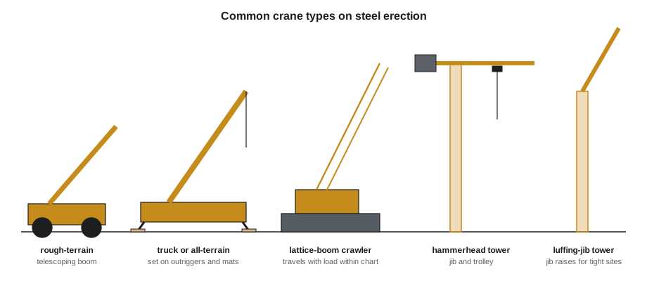
Mobile hydraulic cranes have a telescoping boom of nested steel sections extended and retracted by hydraulic cylinders. They set up quickly, travel between jobs and reach well, which makes them the usual crane for low-rise and mid-rise steel.
- Truck cranes and all-terrain cranes travel on public roads on their own carrier and set up on outriggers. All-terrain cranes have more axles, all-wheel steering and suspension for rough sites, and the largest carry hundreds of tonnes.
- Rough-terrain cranes have a single cab, large tires and short wheelbases for working on unfinished sites. They travel only short distances on their own and are trucked between jobs.
- Boom trucks and knuckle-boom cranes mounted on delivery trucks are small and useful for unloading and setting light pieces. They are cranes, with load charts and operator requirements of their own.
Hydraulic cranes are strong at short radius and lose capacity quickly as the boom extends and the radius grows. They also lose capacity if the boom is not extended in the sequence the chart assumes, and if the outriggers are not set as the chart requires.
Lattice-boom crawler cranes
Lattice-boom cranes have a boom built of steel truss sections pinned together, assembled on site to the length the job needs. On crawler tracks they can travel around a site with a load, within the chart's limits, and they can be very large. Crawler cranes are used for heavy steel, long reaches and big projects such as stadiums, industrial plants and bridges. Assembling and dismantling the boom is itself a hazardous job, done to the maker's procedure under a competent supervisor, with nobody under the boom while pins are removed.
Crawlers need firm, level ground for their tracks over the whole area they will travel, and the ground pressure under the tracks rises sharply on the side the load is on.
Tower cranes
Tower cranes stand on a fixed base or a climbing frame and give a large working area from one position. A hammerhead tower crane has a horizontal jib with a trolley that runs in and out; a luffing-jib tower crane raises and lowers its jib like a boom, which lets it work where space overhead is tight; a self-erecting tower crane folds out from a trailer for smaller jobs. On high-rise steel, the tower crane may be tied to the building and climbed as the frame rises, and the ironworkers often erect and climb the crane themselves under the maker's procedure.
In Ontario, tower cranes have their own trade certificate for operators, and O. Reg. 213/91 adds engineered foundations, inspections before and after erection, climbing inspections and wind and slewing rules for unattended cranes.
Derricks
Before mobile and tower cranes were common, tall steel buildings were erected with guy derricks and stiffleg derricks, which ironworkers moved up the building as it rose. Derricks are still used on some bridge and high-rise work and in places where a crane cannot reach. They are rigged and moved by ironworkers and have their own rules in the crane standards.
Why a crane's capacity changes
A crane's rated capacity is not one number. It changes with every movement of the boom, and it is limited by two different things.
- Structural strength. At short radius, the limit is the strength of the boom, the hoist, the wire rope, the outriggers and the frame. Overload here bends or breaks something, often without warning.
- Stability. At longer radius, the limit is the crane's resistance to tipping. The load times its radius makes an overturning moment; the crane's weight and counterweight times their distance behind the tipping line make the resisting moment. Load charts set capacities below the tipping point by a margin set in the standards.
The tipping line is the line the crane would tip over: the outrigger floats or the edges of the tracks or tires on the load side. Moving the load outward, by lowering the boom, extending it or letting the load swing out, moves the load farther from the tipping line and reduces capacity. A load that swings out a metre at a long radius can overload a crane that was within its chart when the load was still.
Load charts also vary by quadrant, the direction of the boom over the crane. Many mobile cranes are rated differently over the rear, over the side and over the front, because the tipping line is closer or farther in each direction. A pick that is safe over the rear may be over capacity when the boom swings over the side.
Ground and outriggers
A crane is only as stable as what it stands on. Outriggers must be fully extended or set to the positions the chart allows, with the crane level within the maker's limit, which on many cranes is about 1 in 100 or less. Each outrigger float sits on a mat or cribbing large and strong enough to spread its load to the ground without sinking. Ground that looks firm may be soft underneath: fill, backfilled trenches, buried pipes, vaults, basements and recent excavation are all hazards. On a steel job, the crane often sets up close to the new foundations, which means close to backfill.
O. Reg. 213/91 requires the ground bearing capacity to be known before a crane sets up, outriggers to be extended as the load chart requires, and blocking to be strong enough not to fail or settle. Where the crane sits on a structure or on engineered foundations, an engineer designs and inspects them.
Worked problem
Checking an outrigger mat
During the heaviest Ashcroft pick, Dwayne's crane put an estimated 40 t on its most loaded outrigger. The float sits on a 1.5 m × 1.5 m crane mat on the prepared pad, which the geotechnical engineer rated for 200 kPa. Is the mat large enough? What mat area would a 150 kPa soil need?
Show solution
- Outrigger force: 40,000 kg × 9.81 = 392.4 kN.
- Mat area: 1.5 × 1.5 = 2.25 m².
- Bearing pressure: 392.4 ÷ 2.25 = 174.4 kPa, below 200 kPa.
- For 150 kPa: 392.4 ÷ 150 = 2.62 m², a mat about 1.62 m square or larger.
Answer: About 174 kPa, inside the pad's rating. On weaker soil the same crane would need larger mats, or a larger engineered pad. The mat itself must also be stiff enough to spread the load across its whole area.
The figure for the outrigger load comes from the crane maker's outrigger load calculator or the lift planner, not from dividing the crane's weight by four. In a lift over one corner, one outrigger may carry most of the crane's weight plus most of the load.
Wind
Wind pushes on the boom and the load, swings the load and, at a long radius, can overturn a crane. Every crane maker sets a maximum wind speed for operation, often about 32 km/h for many mobile cranes and lower for long booms and large loads, and some charts reduce capacity as the wind rises. The limit is for the wind at the boom tip, which is usually stronger than at ground level, so cranes carry an anemometer at the boom tip or the operator uses a site anemometer and forecast.
Loads with a large surface area, such as deck bundles stood on edge, trusses, wall panels and signs, catch the wind like a sail. The maker's manual explains how to account for them; some lift plans set a much lower wind limit for these loads. At Ashcroft, Carla's lift plan for the lobby truss set a limit of 30 km/h gusts (lesson 12), and Crossbeam stops connecting at 50 km/h gusts whatever the crane's limit.
Other limits and safety devices
- Two-blocking. An anti-two-block device stops the hoist and boom movements before the hook block hits the boom tip. It must be working, and it does not replace watching the block.
- Load moment indicator (rated capacity limiter). It compares the load and radius with the chart and warns or stops the crane near the limit. It is set up for the actual configuration, counterweight and outrigger position; set up wrongly, it gives false confidence.
- Side loading. Booms are designed to lift straight up. Dragging a load sideways, pulling a piece into position with the crane, or swinging fast enough that the load lags behind puts side load on the boom and can buckle it.
- Shock loading. A load that is snatched off the ground, dropped onto slack rigging or caught after a slip puts forces far beyond its weight into the crane and rigging.
- Power lines. Every crane type can reach power lines; lesson 10 covers the distances.
- Travelling with a load. Only cranes rated for it, and only within the chart's travel ratings, may travel with a suspended load, slowly and on firm, level ground, with tag lines.
The operator watches these limits from the cab, but the ironworkers on the ground see things the operator cannot: an outrigger float sinking, a mat cracking, a load swinging toward the side, a block close to the tip. Anyone who sees one gives the stop signal.
Pre-shift inspection
O. Reg. 213/91 requires cranes to be inspected daily, weekly and monthly by a competent worker according to the maker's instructions and the regulation's minimums, with the results in the crane's log. Dwayne starts each shift with his daily inspection before the first pick: the boom, hook, wire rope, safety devices, outriggers and mats, fluid levels and controls.
A crane with a deficiency that is a hazard is taken out of service until it is fixed. The raising gang does not argue with that decision.
Setting up the crane at Ashcroft
Before steel arrived at Ashcroft, Carla, Dwayne and Tallcorn's superintendent, Priscilla Hahn, walked the site with the geotechnical report and the erection drawings. They chose two crane setups on the east side, clear of the new foundations' backfill and of the storm sewer that ran along the north property line, and Tallcorn built a compacted gravel pad for each, rated by the geotechnical engineer. They marked the swing radius of the counterweight, the truck route and the shakeout areas, and checked the overhead lines along the street, which were well outside the crane's reach from both setups.
Each setup was drawn on the site plan with its outrigger positions, mat sizes and the radii to the far corners of the building. That drawing decided the erection sequence: the pieces near the first setup went up first, and the far-end girders waited for the crane to move (lesson 9).
Weather and the crane
Cold weather affects cranes too. Hydraulic oil thickens, steel becomes more brittle at very low temperatures, and ice adds weight to the boom and the load and makes outrigger pads and mats slippery. Many makers set minimum operating temperatures or require warm-up procedures. Snow and ice on a load are part of its weight, and ice can fall from a load or boom onto workers below. Lightning is a hard stop: cranes and steel frames are tall conductors, and Crossbeam stops lifting when lightning is within about 10 km, or as the site plan says, and does not resume until 30 minutes after the last strike.
Cranes on the structure
On some jobs a crane sits on the structure itself: a small crane on a finished floor, a crawler on a bridge deck, or a tower crane tied to the frame. Then the structure must be checked by an engineer for the crane's loads, including outrigger or track loads during lifts, which can be several times the crane's own weight on one point. The crane's loads go into the structure through mats or engineered supports, and nobody sets up a crane on a slab or deck without that check.
Common mistakes
MistakeAssuming a crane's capacity is the number on its side.
InsteadCapacity depends on configuration, radius, boom length and quadrant; check the chart.
MistakeLetting a load swing out at a long radius.
InsteadControl swing with tag lines and smooth motions; swing-out increases radius and overturning moment.
MistakeSetting outriggers on unknown ground.
InsteadKnow the bearing capacity and use mats sized for the outrigger load.
MistakeDividing the crane's weight by four to size mats.
InsteadUse the maker's outrigger load figures for the actual lift.
MistakeDragging steel into place with the hook.
InsteadLift straight up; never side load the boom.
MistakeIgnoring the wind because it is calm at ground level.
InsteadCheck the wind at the boom tip against the maker's and the lift plan's limits.
Summary and key terms
- Mobile hydraulic cranes are quick to set up and reach well; lattice crawlers lift heavy loads and can travel within limits; tower cranes cover a large area from one position.
- Capacity is limited by structural strength at short radius and by stability at longer radius.
- Anything that increases the radius, such as lowering or extending the boom or letting the load swing out, reduces capacity.
- Charts differ by quadrant; a pick safe over the rear may not be safe over the side.
- Outriggers must be set as the chart requires, on mats sized for the ground's bearing capacity.
- Wind, side loading, shock loading and two-blocking are limits too, and the crane is inspected before every shift.
- Tipping line
- The line about which a crane would tip, usually through the outrigger floats or tracks on the load side.
- Quadrant
- The direction of the boom over the crane, such as over the rear, side or front.
- Anti-two-block device
- A device that stops hoisting and boom movements before the hook block reaches the boom tip.
- Load moment indicator
- A system that compares the actual load and radius with the load chart and warns or stops the crane.
- Crane mat
- A timber, steel or composite pad that spreads an outrigger or track load over the ground.
- Side loading
- A sideways force on a crane boom from dragging or swinging a load.
Practice problems
Work each problem on paper first, then reveal the answer to check.
Why does a hydraulic crane lose capacity as the boom extends?
Show answer
The radius grows and the overturning moment increases.
An outrigger carries 30 t on a 1.2 m × 1.2 m mat. What is the bearing pressure?
Show answer
30,000 × 9.81 = 294.3 kN ÷ 1.44 m² ≈ 204 kPa.
What is the tipping line?
Show answer
The line through the outrigger floats or tracks on the load side about which the crane would tip.
Why might a pick that is safe over the rear be unsafe over the side?
Show answer
The tipping line is closer over the side, so the chart capacity is lower.
What should a ground worker do if an outrigger mat begins to sink?
Show answer
Give the stop signal at once.
Lesson quiz · 5 questions
Score 60% or more to complete this lesson.
Create a free account to save your progress, take quizzes and earn a certificate.