
IRW-120 · Lesson 12 of 12 · 28 min
Case study: rigging a long-span truss
▶ Video coming soon A video version of this lesson is on the way.
At Ashcroft Medical Building, the entrance lobby rises two storeys with no column in the middle of it. Across the top of the lobby, at the third floor, a steel truss carries the floor and the column above it over the open space. Truss T-1 is 18.3 m long and 1.8 m deep, and weighs 5,200 kg. It was the longest and most awkward piece on the job, and the only one Crossbeam planned as a critical lift at Ashcroft because of its shape, not its weight. This lesson follows it from the fabricator's drawing to the moment the hook was released, on Wednesday, October 7, 2026, and the review of the lift at the last rigging night on November 12.
Why a truss is different
A truss is a frame of top and bottom chords joined by diagonal and vertical web members. Once it is built into a structure, braced by the floor and the beams framing into it, it is very strong in the direction it was designed for. In the air, on its own, it is not. A long truss is tall and narrow, so it is unstable sideways and can roll over or buckle its top chord if it is lifted the wrong way. Its members are designed for the forces they carry in the finished building; lifting it from the wrong points can put compression into a member designed for tension, or bend a chord between panel points. And it has a large surface area that catches the wind.
For those reasons, trusses are lifted only from pick points that an engineer has checked, with rigging that keeps the sling forces where the engineer expects them, and they are braced before the hook is released.
The engineer's drawing
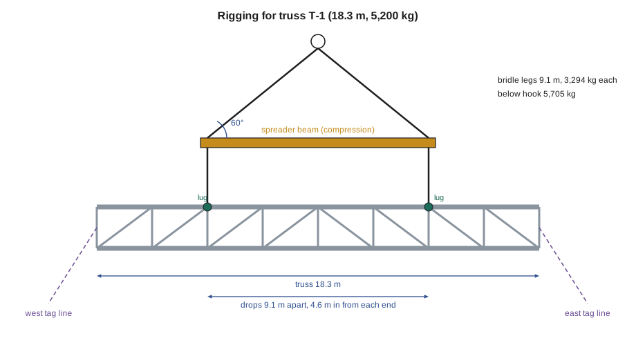
The fabricator, Lakeport Steel Fabricators, had its erection engineer, Odette Hollister, P.Eng., check the truss for lifting and prepare erection drawing E-7. The drawing showed two lifting lugs welded to the top chord at panel points 4.6 m in from each end, the shackle size for each lug, the requirement that the drops be vertical, and a ban on lifting the truss from its bottom chord or from slings choked around the chords. It also showed the temporary bracing needed before release: two struts from the top chord to the third-floor beams already in place, and a tie from the bottom chord to the column at each end.
The truss would bear on seats at its ends, bolted to the two lobby columns. The drawing required four bolts at each end, drawn up wrench-tight, and the bracing installed and checked by the foreperson before the crane let go. That is more than the two-bolt minimum in lesson 11, because the truss is the only thing holding up the column above it.
Planning the lift
Carla wrote the lift plan in the week before, using the crane setup that Dwayne would already be in for the second tier. She started with the weights.
Worked problem
Weights below and on the hook
The truss weighs 5,200 kg with its lugs and seat plates. The spreader beam weighs 410 kg, and the bridle, drops and four shackles weigh 95 kg. The hook block weighs 680 kg. What is the weight below the hook, and what load must be compared with the chart?
Show solution
- Below the hook: 5,200 + 410 + 95 = 5,705 kg.
- With the hook block: 5,705 + 680 = 6,385 kg.
Answer: 5,705 kg below the hook and 6,385 kg against the chart.
Next she checked the crane at the set radius and at the largest radius the truss would pass through. The truss would be picked from its trailer on the east side and swung over the open lobby bay, never over the street or the tower of steel already set.
Worked problem
Checking the crane
Using the SAMPLE chart from lesson 9 with the 30 m boom, the set radius is 16 m (13,900 kg) and the largest radius in the swing is 18 m (11,500 kg). What fraction of chart is used at each?
Show solution
- At 16 m: 6,385 ÷ 13,900 ≈ 0.46, about 46 in 100.
- At 18 m: 6,385 ÷ 11,500 ≈ 0.56, about 56 in 100.
Answer: Well under 75 in 100 everywhere in the swing. By capacity alone this was not a critical lift; it was critical because it was a long, unstable truss with engineered pick points.
Then the rigging. Carla chose a spreader beam long enough to give vertical drops to the two lugs, which are 9.1 m apart, and a two-leg bridle from the hook to the ends of the spreader with legs 9.1 m long. With the bridle legs as long as the spreader, the bridle forms an equilateral triangle and the legs are at 60 degrees.
Worked problem
Forces in the rigging
The weight under the bridle is 5,705 kg. With bridle legs at 60 degrees, what is the tension in each bridle leg and the compression in the spreader? Each drop carries half the truss and a share of the rigging, about 2,620 kg. The bridle legs are 20 mm slings rated 5,100 kg vertical and the drops are 16 mm slings rated 3,550 kg vertical. The spreader is rated for 8,000 kg below it with a 60 degree bridle.
Show solution
- Bridle leg: (5,705 ÷ 2) × 1.155 ≈ 3,294 kg; 3,294 ÷ 5,100 ≈ 65 in 100 of the sling rating.
- Spreader compression: (5,705 ÷ 2) ÷ tan 60° = 2,852.5 ÷ 1.732 ≈ 1,647 kg.
- Drops: 2,620 ÷ 3,550 ≈ 74 in 100 of the sling rating.
- Spreader: 5,705 kg below it, within its 8,000 kg rating.
Answer: Every item is within its rating, and the drops, the most heavily used items, are at about three quarters. The spreader takes the squeeze, so the truss feels only vertical pulls at its lugs, as the engineer required.
The plan also set the conditions: wind gusts at the boom tip no more than 30 km/h, because the truss has a large side area; daylight; the lobby bay and the area under the swing path closed to all trades from 6:30 until the truss was released, with the general contractor's crew holding the barriers; and a planned landing area on cribbing beside the trailer if the lift had to be stopped.
The people were named: Carla as lift director, Dwayne as operator, Nate Okonkwo as signal person on the radio, Andy and Marco connecting at the third floor, tied off to self-retracting lifelines on the beams already set, and Shay and Tobias Reyes, borrowed from the rod gang for the morning, on the tag lines at the west and east ends. Grace would watch the exclusion zone with Priscilla Hahn's crew. Carla and Dwayne signed the plan on Monday, October 5, and Odette reviewed it by email that afternoon.
The day before
The truss arrived on a stretch trailer on Tuesday, October 6, after Grace's morning toolbox talk. Carla and Shay checked it against E-7 before it was unloaded: piece mark, lug positions, lug welds without visible cracks, seat plates, and no damage from shipping. It stayed on the trailer, chained down, to be picked directly the next morning. The spreader beam, slings and shackles were laid out on cribbing next to the trailer, and Carla inspected every item and checked its tag against the plan. One shackle's pin was stiff; she replaced the shackle with a spare of the same rating rather than force it.
The lift
On Wednesday, October 7, the forecast was for light winds, about 8 km/h gusting to 18 km/h, and a dry morning.
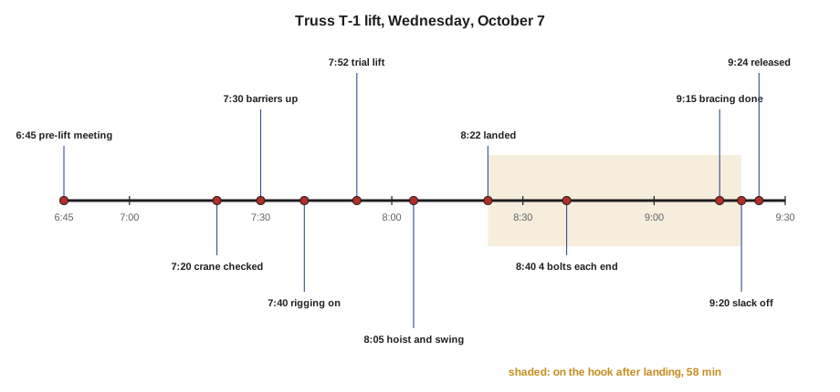
- 6:45. Carla held the pre-lift meeting at the gang box with everyone named in the plan. She walked through the weights, the rigging, the path, each person's job, the radio channel, the stop conditions and the emergency landing area. She asked each person to say their job back. Shay's was: "West tag line, from the lay-down side, never under the truss, let go if it pulls."
- 7:20. Dwayne finished his pre-shift inspection and reported the crane ready, with the boom-tip wind at 9 km/h.
- 7:30. The barriers went up around the lobby bay and the swing path, and Grace confirmed the zone was clear.
- 7:40. The rigging was connected: bridle to the hook, spreader to the bridle, drops from the spreader to the lugs with bolt-type shackles, pins secured with nuts and cotter pins. Carla checked every connection and the tag lines were tied to the ends of the truss.
- 7:52. Trial lift. Dwayne took the weight and lifted the truss about 150 mm off the trailer and held it for five minutes. Carla checked that the drops were vertical, the shackles were seated, the spreader was level and the truss hung level; it was about 40 mm low at the east end, well within the 180 mm the engineer allowed. Dwayne checked his load reading, the outriggers and the mats. Both said they were satisfied.
- 8:05. The truss was hoisted clear of the trailer and swung slowly west over the lobby bay. Shay and Tobias kept it from rotating, walking with it outside its path. Nate gave a running count on the radio.
- 8:22. The truss was lowered the last metre slowly onto its seats, with Andy and Marco guiding the ends by hand on the sides of the chords, palms flat, and drift pins aligning the first holes.
- 8:40. Four bolts were wrench-tight at each end. The truss stayed on the hook.
- 8:40 to 9:15. Andy and Marco fitted the two top-chord struts to the third-floor beams and the bottom-chord ties to the columns, bolting each one as E-7 showed.
- 9:18. Carla checked the bolts and bracing against E-7, item by item.
- 9:20. Carla told Nate to take the load off slowly. Dwayne slacked the hook a little at a time while everyone watched the truss take its own weight on the seats and braces.
- 9:24. The drops were unshackled, the empty rigging was hoisted clear and set down on the cribbing, and the barriers came down at 9:30.
The truss had been on the hook for almost an hour after it was landed. No one suggested releasing it earlier.
What made it go well
At the November 12 rigging night, Carla asked the apprentices what had made the lift go well. Their list was short, and almost all of it was done before the truss left the ground.
- The weight came from the fabricator's drawing and was checked.
- The pick points came from an engineer, and the rigging was chosen to load them the way the engineer intended.
- Every item of rigging was inspected the day before, and a doubtful shackle was replaced, not forced.
- The crane was checked at the largest radius in the swing, not just the set radius.
- The wind, the area and the people were all controlled by the plan, and everyone knew the stop conditions.
- The trial lift was a real check, with both the lift director and the operator saying they were satisfied.
- The hook stayed on until the drawing's conditions were met.
What could have gone wrong
Carla also asked them to name what could have turned the same lift into an accident. Each answer matched a lesson in the course.
- A wrong weight, if someone had guessed from the truss's size (lesson 4).
- Slings choked around the chords, putting forces into the truss the engineer had not checked, or a bridle straight to the lugs with no spreader, squeezing the top chord (lessons 5 and 6).
- A shackle with a bent pin, or a screw pin that backed out as the truss rotated (lesson 3).
- A swing path over the street or over people, or a radius in the swing larger than the one checked (lessons 9 and 10).
- A gust catching the truss's side area on the way up (lesson 8).
- A tag line wrapped around a wrist, or a handler under the truss (lesson 11).
- Two people giving signals, or a stop called too late (lesson 7).
- Releasing the hook after the first bolts, before the bracing was in (lesson 11).
Worked problem
A what-if for the review
Suppose the bridle had been made with 6.4 m legs to the same 9.1 m spreader, to save headroom. What would the sling angle and the tension in each bridle leg have been?
Show solution
- Half the spreader length: 4.55 m.
- Hook height above the spreader: √(6.4² − 4.55²) = √(40.96 − 20.70) = √20.26 ≈ 4.50 m.
- sin θ = 4.50 ÷ 6.4 ≈ 0.703, so θ ≈ 45 degrees.
- Tension: 2,852.5 × (6.4 ÷ 4.50) ≈ 2,852.5 × 1.422 ≈ 4,056 kg, about 80 in 100 of the 5,100 kg sling rating.
Answer: About 45 degrees and about 80 in 100 of the sling rating, still within it, but with much less margin, and with the spreader compression nearly doubled, to about the same value as each leg's vertical share. Shorter legs would have needed a check of the spreader's rating at the flatter angle too. The longer legs cost a little headroom and bought a large margin.
The case study and the course
Truss T-1 used almost every part of this course in one lift: the roles of the lift team (lesson 1), slings and their ratings (lesson 2), shackles and a spreader (lesson 3), weights (lesson 4), sling angles and the squeeze on a long member (lesson 5), vertical hitches at engineered points instead of chokers (lesson 6), radio signals and a running count (lesson 7), the crane's limits and wind (lesson 8), the chart and the lift plan (lesson 9), critical lift controls (lesson 10), and tag lines, landing and release (lesson 11). Shay kept a copy of the lift plan in his binder. "Next time," Carla told him, "you will help write one."
Common mistakes
MistakeLifting a truss from slings choked around its chords.
InsteadLift only from the engineer's pick points, with the rigging the drawing shows.
MistakeUsing a bridle direct to the lugs on a long truss.
InsteadUse a spreader so the drops are vertical and the truss is not squeezed.
MistakeChecking the crane only at the set radius.
InsteadCheck the largest radius and lowest-rated quadrant in the swing.
MistakeForcing a stiff shackle pin into place.
InsteadReplace a doubtful shackle with a good one of the same rating.
MistakeReleasing a truss once it is bolted at the seats.
InsteadKeep the hook on until the drawing's bolting and bracing are complete and checked.
MistakeTreating a lift as routine because it is well under capacity.
InsteadApply all the critical lift criteria, including the shape and stability of the piece.
Summary and key terms
- Long trusses are unstable sideways, sensitive to where they are lifted, and catch the wind.
- Trusses are lifted only from engineered pick points, with rigging that loads them as the engineer intended, often with a spreader and vertical drops.
- The lift plan covered weights, crane capacity at the set and largest radii, rigging forces, wind, the exclusion zone, the people and the stop conditions.
- Every rigging item was inspected and checked against the plan before the lift, and a doubtful shackle was replaced.
- The trial lift checked balance, rigging and crane, with the lift director and operator both satisfied.
- The truss stayed on the hook until the drawing's bolts and bracing were in and checked.
- Truss
- A frame of top and bottom chords joined by web members, used to span long distances.
- Chord
- One of the main top or bottom members of a truss.
- Panel point
- A point on a truss where web members meet a chord.
- Erection drawing
- A drawing that shows how and in what order steel is to be erected, including pick points and bracing.
- Lifting lug
- A plate welded to a piece to give an engineered lifting point.
- Temporary bracing
- Bracing installed during erection to keep steel stable until the permanent structure is complete.
Practice problems
Work each problem on paper first, then reveal the answer to check.
Why was truss T-1 treated as a critical lift when it used under 60 in 100 of chart?
Show answer
Because it was a long, unstable truss with engineered pick points.
What is the tension in each bridle leg for 4,000 kg under a bridle at 60 degrees?
Show answer
(4,000 ÷ 2) × 1.155 = 2,310 kg.
What is the spreader compression in the same case?
Show answer
2,000 ÷ tan 60° = 2,000 ÷ 1.732 ≈ 1,155 kg.
What did the trial lift check?
Show answer
Balance, vertical drops, seated shackles, a level spreader and truss, and the crane's load reading, outriggers and mats.
Why did the truss stay on the hook for nearly an hour after landing?
Show answer
The drawing required four bolts at each end and the temporary bracing before release.
Lesson quiz · 5 questions
Score 60% or more to complete this lesson.
Create a free account to save your progress, take quizzes and earn a certificate.