
INS-310 · Lesson 9 of 12 · 21 min
Equipment insulation for cold service
▶ Video coming soon A video version of this lesson is on the way.
On Tuesday, November 10, Priya joined Tomasz's crew in the Mountview penthouse, where they were jacketing the chilled water piping that Devon and Tessa had insulated in October. Before the jacketing could finish, the chilled water equipment itself had to be insulated: a vertical buffer tank about 900 mm across and 2.4 m tall, an air separator, two pump bodies and a chemical pot feeder, all at about 7 °C in a room designed for 27 °C and 70 in 100 relative humidity. INS-210 had worked out the dew point for that room: about 21 °C. "On hot work, a gap costs you heat," Tomasz told her. "On cold work, a gap costs you the whole system. Water gets in, it freezes or it soaks, and nothing you did around it matters any more."
Cold service means equipment that runs below the temperature of the surrounding air: chilled water, brine and glycol, refrigeration, and the very cold systems of the food, chemical and gas industries. INS-320 covers cold, refrigeration and cryogenic systems in depth. This lesson introduces cold equipment: why it is different from hot equipment, which materials suit it, how the vapour retarder must be built and kept continuous around the many details of a vessel or pump, and how to check that the insulation is thick enough to stop condensation.
Why cold is different
Air always carries some water vapour, and water vapour always moves from where there is more of it to where there is less: from warm, humid air toward a cold surface. This vapour drive pushes moisture into the insulation on cold equipment all the time, from the outside in. If it reaches a layer that is colder than the dew point, it condenses; if that layer is below freezing, it freezes. Over months and years, the water and ice build up, the insulation's thermal resistance falls, the outer surface gets colder, more water condenses on it and in it, and eventually the jacket sweats, drips and corrodes, and the equipment underneath corrodes too.
On hot equipment the opposite happens: the vapour drive is outward and the heat dries the insulation. That is why hot insulation can tolerate small gaps and fibrous materials without a vapour retarder, and why cold insulation cannot. On cold equipment, the insulation system has two jobs: insulate enough to keep the outer surface above the dew point, and stop water vapour reaching the cold surface at all.
Materials for cold equipment
The best materials for cold equipment resist water vapour themselves, so that a small breach in the vapour retarder does not soak the whole system. These are the closed-cell materials:
- Cellular glass, which is impermeable to water vapour, does not absorb water, and is rigid and strong. It is used on chilled water, refrigeration and cryogenic vessels, often with sealed joints.
- Flexible elastomeric foam sheet and tube, which is closed-cell and low in permeance, bonds to the surface with contact adhesive, and is common on chilled water equipment and pumps in buildings.
- Polyisocyanurate and polyurethane foams and phenolic foam, in blocks, segments and boards, used on chilled water and refrigeration vessels, always with a vapour retarder.
Fibrous materials such as glass fibre are used on some chilled water equipment with a factory vapour retarder facing and sealed joints, but any break in the facing lets water into an open fibre structure where it collects. Many specifications therefore call for closed-cell materials on cold equipment, especially in humid spaces.
The vapour retarder
The vapour retarder is the continuous layer, on the warm side of the insulation, that slows water vapour to a very low rate. It may be a factory jacket or facing, a sheet membrane, a vapour retarder mastic or coating, or the outer skin of a closed-cell material with its seams sealed. Whatever it is, it must be:
- Continuous, with every seam, joint and lap sealed and no holes.
- On the warm side, which on cold equipment is the outside.
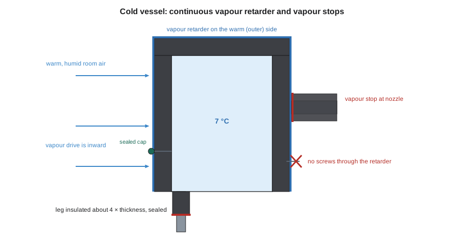
- Unbroken by fasteners. Screws, rivets, staples and welded pins through the vapour retarder are leaks. Where insulation must be held by pins on cold equipment, adhesive-based pins are used and every pin head and washer is sealed over with vapour retarder mastic or a sealed cap. Bands go outside the vapour retarder and do not pierce it.
- Protected. Jacket or a hard coating over the vapour retarder keeps it from being punctured by tools, ladders and people.
On vessels, the vapour retarder is also divided into sections by vapour stops: sealed bands where the insulation is bonded and sealed to the surface, so that if one section is breached, the moisture cannot travel along the whole vessel. Vapour stops go at every termination, such as the ends of the insulation, nozzles, manways and supports, and on large vessels at intervals as the specification requires.
Details on cold equipment
Most failures on cold equipment start at details, not on the plain shell. The common details are:
- Nozzles and piping connections. The pipe insulation and the vessel insulation meet here, and the vapour retarders of both must be joined and sealed. A vapour stop at the nozzle separates the two systems.
- Supports, legs, saddles and lugs. These carry cold from the vessel into the structure. A bare steel leg on a cold tank sweats and frosts from the vessel down. Common practice is to insulate supports and other attachments for a distance from the vessel, often given in the specification as about four times the insulation thickness, and seal the end of that insulation with a vapour stop. Where a support rests on cold insulation rather than on the vessel, high-density inserts carry the load, as INS-130 described for pipe shields.
- Manways and inspection openings. These need sealed removable covers, which must be resealed after every opening (lesson 4).
- Instruments, thermowells and gauges. Their stems carry cold out; insulate them as far as possible and seal around their heads so they stay readable.
- Pumps. Pump bodies on chilled water are usually insulated with removable, sealed covers, often boxes of closed-cell sheet or PVC-jacketed covers that seal at their edges, so the mechanics can reach seals and bolts. The motor and bearing housing are not insulated.
- Bottom heads and drains. Condensation from any leak above runs down to the bottom; the bottom head and its drain connection are often where water collects. Seal the bottom carefully and keep drain valves accessible.
How thick is thick enough?
On cold equipment, the insulation must be thick enough that its outer surface stays above the dew point of the surrounding air on the worst design day, with a margin. If the outer surface falls below the dew point, water condenses on the jacket even if the vapour retarder is perfect. The check uses the same heat-flow reasoning as INS-120: heat flows from the room through the surface film and the insulation to the cold equipment, and the surface temperature is the room temperature minus the temperature drop across the surface film.
Worked problem
Checking the buffer tank against condensation
The buffer tank runs at 7 °C. The penthouse design condition is 27 °C and 70 in 100 relative humidity, with a dew point of about 21 °C. The schedule calls for 38 mm of elastomeric sheet (k about 0.036 W/m·K) in two 19 mm layers. Treat the tank wall as flat and use a surface film coefficient of 8 W/m²·K, a low value for still air that makes the check on the safe side. What is the outer surface temperature with 38 mm, and with one 19 mm layer?
Show solution
- Resistance of 38 mm = 0.038 ÷ 0.036 = 1.056 m²·K/W; surface film = 1 ÷ 8 = 0.125. Total = 1.181.
- Heat flow = (27 − 7) ÷ 1.181 = 16.9 W/m².
- Surface temperature = 27 − 16.9 × 0.125 = 27 − 2.1 = 24.9 °C, which is 3.9 °C above the 21 °C dew point.
- With 19 mm: 0.019 ÷ 0.036 = 0.528; total 0.653; flow = 20 ÷ 0.653 = 30.6 W/m²; surface = 27 − 30.6 × 0.125 = 23.2 °C, only 2.2 °C above the dew point.
Answer: With 38 mm the surface is about 25 °C, a safe margin above the 21 °C dew point; one 19 mm layer leaves too little margin.
This simple check treats the tank wall as flat, which slightly underestimates the margin on a curved surface, and uses typical values. INS-410 shows the full method, including curved surfaces and the effect of the jacket's emittance. The important idea is that the margin above the dew point is what protects the system when conditions are worse than expected or the insulation ages, so designers use conservative values.
Installing elastomeric sheet on cold equipment
Elastomeric sheet is the usual material for chilled water equipment in buildings. The maker's instructions govern, but the method is:
- Clean and dry the surface. Insulate only when the surface is above the dew point, which on chilled water usually means with the system off or the equipment warmed; adhesive will not bond to a wet or sweating surface.
- Cut the sheet to the measured pattern, with the circumference measured at the sheet's mid-thickness so the seams close without stretching.
- Apply the maker's contact adhesive to both the surface and the sheet for full bonding on cold work, let it become tacky, then press the sheet on, working from one edge so no air is trapped.
- Seal every seam by applying adhesive to both cut edges and pressing them together under slight compression, so the seam is bonded across its full depth.
- Apply a second layer with all seams offset from the first layer's seams, bonded the same way.
- Insulate nozzles, the air separator, the pot feeder and the supports, joining each to the vessel insulation with bonded, sealed seams.
- Coat or jacket the outer surface as the specification requires; elastomeric foam outdoors or in sunlight needs a protective coating or jacket, and in mechanical rooms a PVC jacket protects it from damage.
Never stretch elastomeric sheet to close a seam; stretched foam pulls back over time and opens the seam. And never leave a cold surface partly insulated overnight in humid weather: water condenses on the exposed metal, and the next layer goes on over wet steel. INS-130 gave the rule: install only what you can seal the same day.
What Priya found
On Tuesday morning, before starting, Tomasz walked Priya round the penthouse equipment with a flashlight. The buffer tank's legs had been bolted to the housekeeping pad with bare steel shims, and nobody had planned to insulate the legs; Tomasz marked them for insulation 150 mm down from the tank, sealed with a vapour stop, which is about four times the 38 mm thickness, and added it to the day's list. The pot feeder's fill valve had been mounted tight against the tank, so its handle would have been buried; Harcourt moved it on Wednesday. The air separator had a factory nameplate that the schedule did not mention; Priya cut a framed opening around it and sealed its edges, as lesson 11 describes. By Thursday afternoon, the tank, the separator, the feeder and the pump covers were done, and the PVC jacket went on over all of them on Friday, the last day of Tomasz's penthouse jacketing week.
Removable covers on cold pumps
Chilled water pumps need their seals, couplings and bolts reached, so their bodies get removable covers rather than fixed insulation. A good cold pump cover is made in two or more parts that fit around the pump volute and its suction and discharge flanges, with a closed-cell lining against the metal and a sealed outer skin. The joints between the parts and the edges where the cover meets the pipe insulation carry flaps of vapour retarder that are sealed with tape or a sealant the maker approves each time the cover is closed. The cover stops short of the motor, the coupling guard and the bearing housing, which must stay bare to cool and to be inspected. A drain at the lowest point of the cover lets any condensate that does form run out where it can be seen, rather than collect against the pump.
Common mistakes
MistakeUsing screws or rivets through the jacket and vapour retarder on cold equipment.
InsteadUse bands, adhesive and sealed laps; nothing may pierce the vapour retarder.
MistakeLeaving support legs and lugs bare on a cold tank.
InsteadInsulate attachments for a distance from the vessel, typically about four times the insulation thickness, and seal the end.
MistakeBonding insulation to a sweating surface.
InsteadInsulate only when the surface is dry and above the dew point.
MistakeStretching elastomeric sheet to close a seam.
InsteadCut it to the mid-thickness circumference and bond the seam under slight compression.
MistakeLeaving cold equipment partly insulated overnight.
InsteadInstall only what can be sealed the same day.
Summary and key terms
- On cold equipment, water vapour is driven inward all the time; any gap lets water and ice build up and ruins the system.
- Closed-cell materials, such as cellular glass, elastomeric foam and rigid foams, are preferred; fibrous materials need perfect facings.
- The vapour retarder must be continuous, on the outside, unpierced by fasteners, protected, and divided by vapour stops.
- Details fail first: nozzles, supports, manways, instruments, pumps and bottom heads.
- Insulation must keep the outer surface above the dew point on the design day, with a margin.
- Install only on dry surfaces, bond seams fully, offset layers, and seal what you install the same day.
- Cold service
- Equipment or piping that runs below the temperature of the surrounding air.
- Vapour drive
- The movement of water vapour from warm, humid air toward a colder surface.
- Vapour retarder
- A continuous layer on the warm side of the insulation that slows the passage of water vapour.
- Vapour stop
- A sealed band where the insulation and vapour retarder are bonded to the surface to divide the system into sections.
- Closed-cell insulation
- Insulation whose cells are sealed, so it resists water and water vapour.
- Dew point
- The temperature at which water vapour in the air begins to condense.
- Surface film coefficient
- A number describing how readily heat passes between a surface and the surrounding air.
Practice problems
Work each problem on paper first, then reveal the answer to check.
Which way does the vapour drive push on cold equipment?
Show answer
Inward, from the warm room toward the cold surface.
A tank at 5 °C is in a room at 25 °C. With insulation resistance 1.0 and surface film 0.125 m²·K/W, what is the surface temperature?
Show answer
Flow = 20 ÷ 1.125 = 17.8 W/m²; surface = 25 − 17.8 × 0.125 = 22.8 °C.
How far are cold tank legs typically insulated from the vessel if the insulation is 50 mm?
Show answer
About four times the thickness, 200 mm, or as specified.
Why are adhesive-based pins used on cold equipment instead of welded pins?
Show answer
Welding damages coatings and pins conduct cold; adhesive pins can be sealed over without piercing the retarder from inside.
Why are seams in the second layer offset from the first?
Show answer
So no seam runs straight through to the cold surface.
Lesson quiz · 5 questions
Score 60% or more to complete this lesson.
Create a free account to save your progress, take quizzes and earn a certificate.