
INS-310 · Lesson 4 of 12 · 23 min
Heat exchangers and removable sections
▶ Video coming soon A video version of this lesson is on the way.
On Monday, November 9, the first day after the outage, Marcel and Devon were measuring valves in the Kellerton boiler house for blanket covers. Wendell took Priya to the other end of the same room, to the sanitation hot water heat exchanger that the rebuilt pressure-reducing station feeds. Its shell had been insulated years ago and was in fair shape; its two ends were bare steel and too hot to touch. "They left the ends bare because the plant opens them," Wendell said. "Then nobody came back to cover them. The plant's been heating this room with them ever since." Lou Brisebois wanted removable covers that the maintenance crew could take off and put back without calling Coldstream.
Heat exchangers are among the most common pieces of equipment an insulator meets, and they are designed to be opened. Their tubes are cleaned, their plates are re-gasketed, their bundles are pulled out for inspection. Insulation that cannot come off without being destroyed will be destroyed, usually by the first maintenance crew that needs access, and is rarely put back. This lesson describes the main kinds of heat exchanger, what parts must stay accessible, and how removable sections are made and fitted. INS-330 goes further into designing and making removable blanket covers.
Kinds of heat exchangers
A heat exchanger moves heat from one fluid to another without mixing them. The insulator needs to know which parts are hot or cold, which parts come apart, and which way the maintenance crew will need to pull things out.
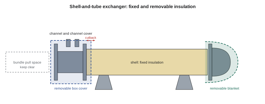
- Shell-and-tube exchangers have a bundle of tubes inside a cylindrical shell. One fluid flows through the tubes, the other around them inside the shell. At one or both ends is a channel (or channel head), a short chamber bolted to the shell with nozzles for the tube-side fluid, closed by a bolted channel cover. At the far end there may be a second channel, a rounded bonnet, or a removable shell cover over a floating head. To clean or inspect the tubes, the channel cover is unbolted; to inspect the bundle, the whole bundle is pulled out through the channel end, which needs a clear space in front of the exchanger at least as long as the bundle. Steam-to-water heaters, oil coolers and many process exchangers are shell-and-tube.
- Plate heat exchangers are a stack of thin corrugated plates with gaskets, clamped between a fixed frame plate and a movable pressure plate by long tie bolts. The fluids flow in alternate channels between the plates. To service them, the tie bolts are loosened and the plates slide apart along carrying bars. They are compact and common on domestic hot water, heating water and food processes.
- Double-pipe and coil exchangers, air coils, condensers and other types appear too. Many come from the maker with their own insulation or none, and the specification says which are insulated on site.
What must stay accessible
Before insulating any exchanger, find out from the drawings, the maker's manual and the plant's maintenance crew which parts they open, and how often. On a shell-and-tube exchanger, the usual list is:
- The channel cover and its bolting, which come off for tube cleaning, often every year or two.
- The bolted joints between channel and shell, and between the shell and any bonnet or shell cover, which are opened for bundle removal.
- The bundle pull space in front of the removable end, which must stay clear of insulation, jacket, pipe and anything else.
- The nameplate, which an inspector must be able to read (lesson 11).
- Relief valves, vents, drains, thermometer wells, pressure gauges and any other instrument connections, which must not be buried.
On a plate exchanger, the tie bolts and the carrying bars must stay free so the pressure plate can slide back, and the plates themselves must be reachable. Many plate exchangers come with an optional insulation shroud made by the maker, a set of insulated panels that fit around the plate pack and are held by latches; where the specification calls for one, it is usually best to use it rather than build a field box.
Everything else, such as the shell between its bolted ends, the nozzles and the connecting piping, is normally insulated permanently, like any other vessel or pipe.
Fixed insulation and the cutback
Where permanent insulation meets a bolted joint, it is stopped short of the flange so the bolts can be removed without damaging it. INS-210 called this the cutback, and the same rule works on equipment: stop the fixed insulation far enough back from the flange face that the longest stud can be withdrawn, typically the stud length plus about 25 mm. The end of the fixed insulation is closed with a sealed end cap or a finished bevel, and the removable cover laps over it.
On a horizontal exchanger, the shell is insulated like a horizontal vessel (lesson 2), with bands, and the saddles are insulated around and sealed. Nozzles are insulated like branch pipes, out to their flanges, again with a cutback at each flange.
Kinds of removable sections
A removable section is a piece of insulation built so it can be taken off and refitted without tools, or with simple hand tools, and without damage. Equipment uses three main types:
- Removable blanket covers are sewn jackets of high-temperature cloth filled with insulation, shaped to fit the part, and closed with straps and buckles, hook-and-loop strips, lacing hooks or stainless springs. They are light, fit irregular shapes and can be made in the shop from field measurements. They are the usual choice for channel heads, bonnets, valves and turbine casings. INS-210 introduced them for valves; INS-330 covers how they are patterned and made.
- Metal box covers are rigid boxes of aluminum or stainless jacket, lined with insulation and made in two or more parts that bolt, latch or band together around the part. They are tougher than blankets and suit outdoor work, washdown areas and parts that are opened often.
- Removable panels are flat or curved insulated panels held by latches, quick-release fasteners or screws, used on large flat ends, access doors, manways and the maker's shrouds for plate exchangers.
Whatever the type, a good removable section has a few things in common. It is light enough for one or two people to lift. It has handles or lifting tabs if it is heavy. It closes with hardware that survives being used many times. It is marked with a tag that says where it goes, and which way up. And it overlaps the fixed insulation, or has a flap that does, so that no bare band is left between them when it is in place.
Measuring for covers
Removable covers are made in the shop from measurements taken on site, so the measurements must be complete and accurate. For an exchanger channel, measure:
- The outside diameter of each flange and of the channel barrel between them.
- The length of the channel from the shell flange to the outside of the channel cover, including the bolt ends.
- The length of the longest stud, to set the cutback on the fixed insulation.
- The position, size and angle of every nozzle, drain, vent, gauge and nameplate on the part, measured from a reference such as the top centre line and the shell flange face.
- The temperature of the part and any limits on the cover's outer surface temperature.
Marcel's measuring kit, the canvas bag INS-210 described, has the tools for this: tapes, a flexible rule, a sketch pad with pre-drawn outlines of common shapes, a protractor for nozzle angles, and a camera for photographs with a tape held in view. Each measured part gets a cover number before anyone leaves the site.
Worked problem
A blanket cover for the channel
The exchanger's channel flanges are 597 mm across and the channel barrel between them is 500 mm long. The studs are 125 mm long. The cover is a sewn blanket with 50 mm of insulation, made to fit over the flanges with 13 mm clearance all round, with a 75 mm overlap at its closure. It runs from the end of the fixed shell insulation to the channel cover, and has a flat end disc over the cover. What are the cutback on the shell, the inside diameter and cut width of the cover, its length, and the size of the end disc?
Show solution
- Cutback = stud length + 25 mm = 125 + 25 = 150 mm from the shell flange face.
- Inside diameter = 597 + 2 × 13 = 623 mm.
- Inner circumference = π × 623 = 1,957 mm; cut width with the overlap = 1,957 + 75 = 2,032 mm.
- Length = cutback 150 + channel 500 = 650 mm along the inner face.
- End disc outer diameter = 623 + 2 × 50 = 723 mm, so it closes over the end of the cylinder part.
Answer: Cut back the shell insulation 150 mm; make the cover 623 mm inside, 2,032 mm wide and 650 mm long, with a 723 mm end disc.
The pattern maker in the shop turns this into a sewn cover with the nozzle holes cut where the sketch puts them, closing flaps over each nozzle, and straps spaced along the overlap. INS-330 shows how.
Why it is worth covering the ends
The ends of an exchanger are small compared with its shell, but bare steel loses a great deal of heat, and covers pay for themselves quickly. They also make the space safer: a bare channel at heating water or steam temperature can burn anyone who brushes against it.
Worked problem
Heat saved by covering the exchanger ends
The bare channel and bonnet of the Kellerton exchanger have a combined surface of about 2.2 m² at about 80 °C in a room at 20 °C. Bare steel at this temperature loses about 900 W/m². With 50 mm blanket covers, the loss falls to about 45 W/m². The exchanger runs about 6,000 hours a year. How much heat do the covers save in a year?
Show solution
- Saving per square metre = 900 − 45 = 855 W/m².
- Saving = 855 × 2.2 = 1,881 W, about 1.9 kW.
- Yearly saving = 1.881 kW × 6,000 h = 11,286 kWh.
- In gigajoules: 11,286 × 0.0036 = 40.6 GJ of heat a year, before boiler losses.
Answer: About 1.9 kW, or about 41 GJ of heat a year.
The heat loss figures in this example are typical values for bare and insulated steel at these temperatures; INS-410 shows how such figures are calculated. The point here is the size of the saving: two covers that the maintenance crew can take off in a few minutes save as much heat as several metres of insulated pipe.
Fitting and refitting removable sections
When the covers arrive, fit them as a test before the job is closed: check the fit at every nozzle and gauge, check that the closures reach, check that the cover overlaps the fixed insulation, and check that the bolts and nameplate can be reached by opening only the cover meant for them. Then train the people who will remove them. A short handover with the plant's maintenance crew, showing them how each cover comes off, where to put it while they work, and how it goes back on, does more to keep covers in service than any specification.
Each cover should carry a permanent tag with its number, the equipment tag, and an arrow or note for orientation. Keep a cover list with the measurements, so a damaged cover can be remade without measuring again. On cold equipment, removable covers must reseal: their edges carry a sealed vapour retarder flap, and the plant must reseal them after each opening, as lesson 9 explains. A cold-service cover left loose after maintenance lets moist air in and the ice that follows will ruin it.
On plate exchangers, the maker's shroud is fitted after the plate pack is tightened and tested, and must not be fastened to the plates or tie bolts in a way that stops them moving. Where a field-built box is used instead, it is built in panels that come off one side at a time, with the frame plate side fixed and the pressure plate side removable.
Back at Kellerton
Wendell and Priya measured the channel, the bonnet, the two shell nozzle flanges and the nameplate, numbered the two covers KF-HX-01 and KF-HX-02, and photographed everything. They found the nameplate half-covered by the old shell insulation and marked it for a framed cut-out. Lou asked whether the covers could be made of something the washdown crew could hose. Wendell suggested a silicone-coated glass cloth outer face, which sheds water, with stainless hardware. The covers are planned to be made in the shop with the valve blankets and delivered on November 30, and Wendell plans to fit them himself and show Lou's crew how they come off.
Common mistakes
MistakeInsulating over a channel cover or a bolted joint permanently.
InsteadCut back the fixed insulation and use a removable section.
MistakeBlocking the bundle pull space with pipe insulation or jacket.
InsteadKeep the space in front of the removable end clear.
MistakeMaking a removable cover too heavy to handle.
InsteadSplit it into sections and add handles.
MistakeLeaving a bare band between the removable cover and the fixed insulation.
InsteadMake the cover overlap the fixed insulation.
MistakeDelivering covers without tags or training.
InsteadTag every cover and show the plant crew how to remove and refit it.
Summary and key terms
- Heat exchangers are built to be opened; insulate them so they can be.
- Shell-and-tube exchangers open at the channel cover and bolted ends, and need bundle pull space; plate exchangers need free tie bolts and carrying bars.
- Insulate the shell, nozzles and piping permanently, with a cutback of stud length plus about 25 mm (1 in) at each bolted joint.
- Cover the opened parts with removable blankets, metal box covers or panels that overlap the fixed insulation.
- Measure completely, number every cover, and keep a cover list.
- Test-fit the covers, tag them and train the plant crew; on cold service, make covers reseal.
- Shell-and-tube exchanger
- An exchanger with a tube bundle inside a cylindrical shell.
- Channel
- The bolted chamber at the end of a shell-and-tube exchanger that carries the tube-side nozzles.
- Channel cover
- The bolted cover that closes the channel.
- Bonnet
- A rounded bolted cover at the end of an exchanger.
- Bundle pull space
- The clear space needed to withdraw a tube bundle.
- Plate heat exchanger
- An exchanger made of a stack of gasketed plates clamped by tie bolts.
- Cutback
- The distance the fixed insulation stops short of a flange so bolts can be removed.
- Removable cover
- Insulation built to be taken off and refitted without damage.
Practice problems
Work each problem on paper first, then reveal the answer to check.
Name three parts of a shell-and-tube exchanger that must stay accessible.
Show answer
Any three of: channel cover and bolts, bolted ends, bundle pull space, nameplate, relief valves and instruments.
Studs are 150 mm long. What is the cutback?
Show answer
150 + 25 = 175 mm.
A cover is 700 mm inside diameter with a 75 mm overlap. What is its cut width?
Show answer
π × 700 + 75 = 2,199 + 75 = 2,274 mm.
A cover saves 800 W for 5,000 hours. How much heat is that?
Show answer
0.8 × 5,000 = 4,000 kWh, about 14.4 GJ.
Why must a removable cover on cold service be resealed after it is opened?
Show answer
Moist air gets in through the open edges and condenses or freezes.
Lesson quiz · 5 questions
Score 60% or more to complete this lesson.
Create a free account to save your progress, take quizzes and earn a certificate.