
HSE-332 · Lesson 4 of 12 · 27 min
Corrosion, hydrates and integrity threats
A new separator or pipeline is strong. Twenty years later the same steel may be thinner, cracked or pitted, and the margin between operating pressure and failure may have shrunk to almost nothing. Most loss-of-containment incidents in facilities and pipelines come not from sudden overpressure but from this slow loss of integrity. Integrity threats are the things that weaken equipment over time or attack it in service: corrosion, erosion, cracking, hydrates, freeze-ups, deposits and mechanical damage. Engineers and inspectors manage these threats through integrity programs, but field workers are the people who see the weeping flange, the frozen drain, the dent in the line and the change in a pressure reading first. This lesson explains the main threats in oil and gas facilities and what workers can do about them.
Why oil and gas fluids are corrosive
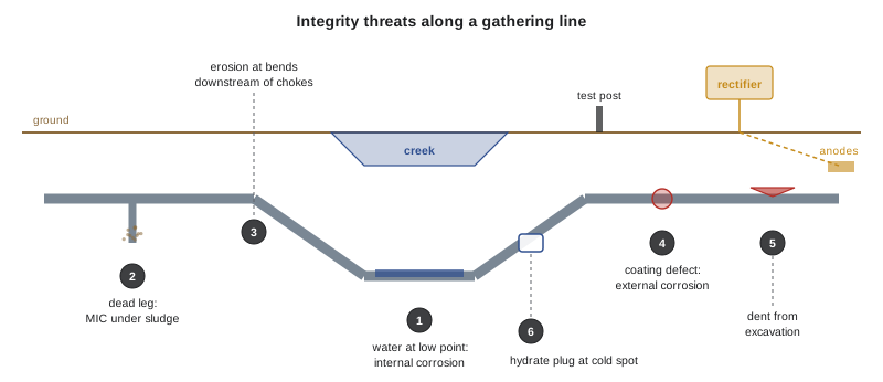
Produced fluids are an ideal recipe for corrosion. Water carries dissolved salts and oxygen; carbon dioxide dissolves in water to form carbonic acid; hydrogen sulphide forms a weak acid and causes cracking in susceptible steels; bacteria thrive in stagnant water; sand and high velocity wear away protective films. Temperature, pressure and flow pattern change how fast each mechanism works. Dry gas at a sales gas specification is barely corrosive; wet sour gas with produced water at a low point in a gathering line can eat through a wall in a few years.
| Mechanism | Cause | What it looks like | Where to expect it |
|---|---|---|---|
| Sweet (CO2) corrosion | Carbonic acid from CO2 in water | Pitting and mesa-shaped attack | Wet gas lines, separators, water handling |
| Sour (H2S) corrosion | H2S in water forms iron sulphide films and pits | Pits under black iron sulphide scale | Sour gas and oil systems |
| Sulphide stress cracking | Hydrogen from H2S embrittles hard steel under stress | Sudden cracks, often at welds or hard spots | Sour service valves, bolts, welds, tubulars |
| Hydrogen-induced cracking and blistering | Hydrogen collects at inclusions in plate steel | Blisters and stepwise cracks | Sour vessels and older line pipe |
| Microbiologically influenced corrosion (MIC) | Bacteria, often sulphate-reducing, under deposits | Deep, localized pits under sludge | Dead legs, tank bottoms, low-flow lines, water systems |
| Oxygen corrosion | Air entering water systems | General rusting and pitting | Water injection, tanks, open drains |
| Erosion and erosion-corrosion | Sand and high velocity remove metal or films | Smooth grooves and thinning at bends | Chokes, elbows, tees, downstream of control valves |
| External corrosion | Soil, moisture and coating damage | Rust and pits on the outside | Buried pipe, insulated piping, supports |
Sour service needs particular care because its failures can be sudden. Sulphide stress cracking can crack a hard steel bolt or valve body without any visible thinning, and the failure may come at normal operating pressure. That is why equipment in sour service must be made from materials that meet NACE MR0175/ISO 15156, why welds in sour service have hardness limits, and why substituting a part from sweet service into a sour system is never allowed without engineering approval. A bolt from the wrong bin can be the weak point that releases a lethal cloud.
Corrosion under insulation is a hidden threat in cold climates. Insulation keeps heat in, but if water gets under it through damaged cladding, the steel beneath can corrode unseen for years. Damaged cladding and wet insulation should be reported, and inspection programs target insulated piping in areas where water collects.
Measuring wall loss and remaining life
Inspectors measure wall thickness with ultrasonic gauges, radiography and, for pipelines, in-line inspection tools. Comparing readings over time gives a corrosion rate, and comparing the current thickness with the minimum required thickness for the pressure gives a remaining life. Inspection programs use the remaining life to schedule the next inspection, commonly at no more than half the remaining life, with other limits set by the code and the company. The program below shows the arithmetic for invented readings on a separator nozzle at Kettle Creek.
# Corrosion rate and remaining life from ultrasonic thickness readings (invented, mm).
readings = {2016: 12.7, 2021: 11.9, 2026: 10.6}   # same monitoring point
t_min = 8.4                                        # minimum required for pressure (illustrative)

years = sorted(readings)
long_rate = (readings[years[0]] - readings[years[-1]]) / (years[-1] - years[0])
short_rate = (readings[years[-2]] - readings[years[-1]]) / (years[-1] - years[-2])
rate = max(long_rate, short_rate)                  # use the more conservative rate
remaining = (readings[years[-1]] - t_min) / rate

print(f"Long-term rate:  {long_rate:.3f} mm/year")
print(f"Short-term rate: {short_rate:.3f} mm/year")
print(f"Governing rate:  {rate:.3f} mm/year")
print(f"Remaining life:  {remaining:.1f} years")
print(f"Next inspection: within {min(remaining / 2, 10):.1f} years (half remaining life, max 10)")Long-term rate: 0.210 mm/year Short-term rate: 0.260 mm/year Governing rate: 0.260 mm/year Remaining life: 8.5 years Next inspection: within 4.2 years (half remaining life, max 10)
The short-term rate is nearly twice the long-term rate, which tells the inspector that something has changed, perhaps more water, more CO2 or a failed inhibitor injection. Using the faster rate gives a remaining life of about six and a half years and an inspection due in about three. Real programs consider many points, uncertainty in the readings and the code's own rules, but the logic is the same: measure, trend and act before the wall reaches its minimum.
Corrosion control
Corrosion is controlled by a combination of design and operation. Materials are chosen for the service, from carbon steel with a corrosion allowance to stainless and corrosion-resistant alloys. Coatings and cathodic protection protect buried and submerged steel from the outside; Lesson 9 explains cathodic protection. Chemical inhibitors are injected to form protective films inside lines. Dehydration keeps gas dry. Pigging removes water and deposits from pipelines, as Lesson 11 describes. Dead legs, short sections of pipe where fluid stagnates, are removed or flushed. Monitoring with coupons, probes and inspection shows whether the controls are working.
Field workers have practical roles in corrosion control. Chemical injection pumps must run and their tanks must stay full; an empty inhibitor tank can mean months of unprotected pipe. Drains on low points and scrubbers must be blown regularly so that water does not sit in the system. Coupon and probe readings must be taken on schedule. Damaged coatings, wet insulation, leaking flanges and unusual deposits should be reported. These small, routine tasks are a large part of what keeps equipment intact.
Hydrates and freeze-ups
Gas hydrates are ice-like solids that form when water and light hydrocarbon gases combine at high pressure and low temperature, well above the normal freezing point of water. They form at chokes and control valves where gas expands and cools, at low points where water collects, and in lines exposed to cold weather. A hydrate can block a line, a valve or an instrument tap, and it is a serious hazard rather than just a nuisance.
Hydrate plugs are dangerous because they trap pressure. A line may have high pressure on one side of the plug and low pressure on the other. If someone depressures only one side, the plug can break loose and travel down the pipe at very high speed, like a projectile, rupturing the line at a bend or blowing out a fitting. Workers have been killed by hydrate plugs released this way. The safe approach is to depressure both sides of a plug slowly and evenly, under a procedure and with the engineer's guidance, and never to apply heat with an open flame to a plugged line. Heating a plug in the middle can release gas into a trapped space and raise pressure sharply.
Prevention is better than removal. Facilities prevent hydrates by dehydrating gas, heating it in line heaters, injecting methanol or glycol at chokes and cold spots, insulating and heat-tracing lines and keeping drains blown. The program below uses a very rough rule-of-thumb curve, for teaching only, to show how the temperature at which hydrates may form rises with pressure, and how much margin a line heater provides. Real hydrate predictions use the gas composition and specialized software.
# Very rough hydrate formation temperature for a lean natural gas (teaching only).
# Uses an illustrative curve fitted to typical published data shapes; not for design.
import math

def hydrate_temp_c(p_kpa):
    return 8.9 * math.log(p_kpa / 1000) + 1.6

for p in (1_000, 2_000, 4_000, 7_000, 10_000):
    print(f"{p:>6,} kPa: hydrates possible below about {hydrate_temp_c(p):5.1f} C")

line_p, gas_t = 7_000, 4.0
margin = gas_t - hydrate_temp_c(line_p)
print(f"Gas at {gas_t} C and {line_p:,} kPa: margin {margin:+.1f} C",
"(hydrate risk)" if margin < 3 else "(ok)")1,000 kPa: hydrates possible below about 1.6 C 2,000 kPa: hydrates possible below about 7.8 C 4,000 kPa: hydrates possible below about 13.9 C 7,000 kPa: hydrates possible below about 18.9 C 10,000 kPa: hydrates possible below about 22.1 C Gas at 4.0 C and 7,000 kPa: margin -14.9 C (hydrate risk)
At high pressure, hydrates can form at temperatures well above freezing, which surprises workers who expect a line to be safe as long as it is above 0 °C (32 °F). A gas line at high pressure on a mild winter day can still plug. When a line plugs, report it and wait for a controlled plan; do not improvise with heat or by bleeding one side.
Ordinary freeze-ups are also hazards. Frozen drains, instrument lines and sight glasses give false readings and can hide a high level that leads to liquid carryover. Water frozen in a dead leg can split the pipe, and the leak appears when the ice melts. Winterization checklists cover heat tracing, insulation, drain blowdowns and methanol injection before cold weather arrives.
Deposits and special threats
Several other substances build up in facilities and create hazards when equipment is opened. Scale, wax and asphaltenes restrict flow and can hide corrosion beneath them. Iron sulphide deposits in sour systems can be pyrophoric, igniting spontaneously when exposed to air, as HSE-330 explained. Sludge and scale from produced water can contain naturally occurring radioactive material. Black powder, a fine iron sulphide and oxide dust, collects in gas pipelines and can foul valves and filters. Lesson 5 covers the chemical side of these hazards and Lesson 11 covers what happens when pigs push them out.
Mechanical damage and external forces
Not all integrity threats come from the fluid. Excavators, augers and vehicles dent and gouge pipe, and a dent that does not leak today can crack later under pressure cycling. Ground movement on slopes and at river crossings bends and buckles pipelines, as Lesson 12's case studies show. Frost heave and thaw settlement move piping supports. Vibration fatigues compressor piping. Lightning, flooding and wildfire threaten above-ground equipment. Integrity programs use patrols, geotechnical monitoring, depth-of-cover surveys and inspection to find these threats; workers help by reporting any contact with a line, however minor, so that it can be inspected.
Worked problem
A frozen line at Kettle Creek
On a −28 °C morning, the operator at Kettle Creek finds that flow from the inlet scrubber's liquid dump line has stopped and the scrubber level is rising. The dump line runs outside to a tank and has a low spot with no heat trace. A colleague suggests using a propane torch to thaw the line. What should the operator do?
Show solution
- Refuse the torch: an open flame near a hydrocarbon line is an ignition source, and heating the middle of a plug can raise trapped pressure sharply.
- Watch the scrubber level and be ready to shut down the compressor or the station inlet before liquid carries over into the compressor.
- Report the plug to the supervisor and control centre and treat it as a possible hydrate or ice plug with pressure trapped on both sides.
- Follow the site procedure for plugged lines: isolate, depressure both sides evenly where possible, and use approved methods such as methanol injection or controlled steam or hot water under a permit.
- After the event, report the missing heat trace so the low spot can be traced, insulated or eliminated.
Answer: The operator protects the compressor, refuses an unsafe thaw and treats the plug as trapped pressure. The lasting fix is to remove the cause, here a cold, untraced low spot.
Common mistakes
MistakeUsing a part from sweet service in a sour system because it fits.
InsteadUse only parts approved for sour service; hard steel can crack suddenly in H2S.
MistakeLetting a chemical injection tank run dry.
InsteadKeep inhibitor and methanol tanks full and pumps running; report failures.
MistakeBleeding pressure off one side of a hydrate plug.
InsteadDepressure both sides slowly and evenly under a procedure.
MistakeThawing a frozen line with an open flame.
InsteadUse approved methods such as methanol, steam or hot water under a permit.
MistakeIgnoring a minor scrape on a buried line during digging.
InsteadReport any contact so the pipe and coating can be inspected.
Summary and key terms
- Produced water, CO2, H2S, bacteria, oxygen, sand and velocity cause corrosion and erosion in facilities and pipelines.
- Sour service can crack hard steel suddenly, so materials must meet NACE MR0175/ISO 15156 and parts must not be substituted.
- Thickness readings over time give corrosion rates and remaining life, which set inspection intervals.
- Corrosion is controlled by materials, coatings, cathodic protection, inhibitors, dehydration, pigging and removing dead legs, with field workers keeping these running.
- Hydrates form at high pressure and low temperature, often above 0 °C, and plugs trap pressure that can launch them like projectiles.
- Deposits such as pyrophoric iron sulphide, NORM scale and black powder create hazards when equipment is opened.
- Mechanical damage, ground movement and vibration also threaten integrity and must be reported.
- Integrity threat
- Anything that weakens equipment over time or attacks it in service.
- Sulphide stress cracking
- Cracking of hard, stressed steel caused by hydrogen from H2S.
- MIC
- Microbiologically influenced corrosion: corrosion driven by bacteria, usually under deposits.
- Corrosion rate
- The rate at which wall thickness is lost, usually in mm or mils per year.
- Remaining life
- The time until wall thickness reaches the minimum required for pressure at the current rate.
- Dead leg
- A section of piping where fluid stagnates.
- Hydrate
- An ice-like solid of water and light hydrocarbon gas that forms at high pressure and low temperature.
- Corrosion under insulation
- Hidden corrosion of steel beneath wet insulation.
Practice problems
Work each problem on paper first, then reveal the answer to check.
Name three ingredients in produced fluids that drive corrosion.
Show answer
Any three of: water, CO2, H2S, oxygen, bacteria, salts, sand.
Why is sulphide stress cracking especially dangerous?
Show answer
It can crack hard steel suddenly without visible thinning, even at normal pressure.
What standard governs materials for sour service?
Show answer
NACE MR0175/ISO 15156.
How is remaining life calculated?
Show answer
Current thickness minus minimum required thickness, divided by the corrosion rate.
Why use the faster of the long-term and short-term corrosion rates?
Show answer
It is more conservative and reflects recent changes in the process.
Give two field tasks that support corrosion control.
Show answer
Any two of: keeping chemical injection running, blowing drains, reading coupons and probes, reporting coating damage or leaks.
Under what conditions do hydrates form?
Show answer
When water and light gas meet at high pressure and low temperature.
Why are hydrate plugs dangerous to remove?
Show answer
They trap pressure and can travel like projectiles if one side is depressured.
What hazard does iron sulphide present when equipment is opened?
Show answer
It can be pyrophoric and ignite on contact with air.
Why should a minor scrape on a buried line be reported?
Show answer
Dents and gouges can crack later under pressure cycling and need inspection.
Lesson quiz · 5 questions
Score 60% or more to complete this lesson.
Create a free account to save your progress, take quizzes and earn a certificate.