
HSE-332 · Lesson 3 of 12 · 28 min
Hazards of pressurized equipment
Almost everything in a facility is under pressure. Separators hold gas at hundreds or thousands of kilopascals, compressors raise it higher, pumps push liquids through piping and pipelines carry both for hundreds of kilometres. Pressure is useful because it moves fluids and makes separation and processing possible. It is dangerous because a pressurized system stores energy, and when containment fails that energy is released in milliseconds. HSE-330 explained why gas stores far more energy than liquid at the same pressure and how pressure releases injure people. This lesson looks at how facility equipment is designed to hold pressure, how it is protected against overpressure, how it fails and what workers can do to keep it inside the pipe.
Pressure terms every worker should know
Several pressures appear on drawings, nameplates and rounds sheets, and confusing them leads to mistakes. The operating pressure is what the equipment normally runs at. The design pressure is the pressure the engineer used to design the vessel or piping, with margin above the operating pressure. The maximum allowable working pressure (MAWP) is the highest pressure the finished vessel may see at the top at a stated temperature; it is stamped on the nameplate and is at least the design pressure. The relief valve set pressure is the pressure at which the relief valve starts to open, normally at or below the MAWP. During a relief event, pressure can rise above the set pressure while the valve is opening fully; the allowed rise is called accumulation, and the codes limit it to small percentages above MAWP. Finally, the hydrostatic test pressure is the higher pressure, typically about 1.3 to 1.5 times MAWP depending on the code, at which a new or repaired vessel is tested with water before it goes into service.
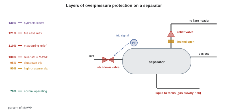
The program below lays out the pressure ladder for an invented separator at the Pinecrest battery. It uses typical code allowances: up to 10 percent accumulation for a single relief valve in an ordinary overpressure case, and up to 21 percent for a fire case. These values are illustrative; the actual limits are set by the applicable code and the engineer's design.
# Pressure ladder for an invented separator (kPa gauge). Allowances are typical, illustrative.
operating = 4_200
mawp = 6_000
set_pressure = mawp                  # relief valve set at MAWP
accum_single = 0.10                  # single valve, non-fire case
accum_fire = 0.21                    # fire case
hydrotest = 1.3 * mawp               # typical modern code ratio

ladder = [
    ("Normal operating", operating),
    ("High-pressure alarm (example)", 0.90 * mawp),
    ("High-pressure shutdown (example)", 0.95 * mawp),
    ("Relief valve set pressure", set_pressure),
    ("Max during relief, non-fire", mawp * (1 + accum_single)),
    ("Max during relief, fire case", mawp * (1 + accum_fire)),
    ("Hydrostatic test pressure", hydrotest),
]
for name, p in ladder:
    print(f"{name:34s} {p:>7,.0f} kPa  ({p/mawp*100:5.1f} % of MAWP)")
print(f"Margin from operating to set pressure: {set_pressure - operating:,.0f} kPa")Normal operating 4,200 kPa ( 70.0 % of MAWP) High-pressure alarm (example) 5,400 kPa ( 90.0 % of MAWP) High-pressure shutdown (example) 5,700 kPa ( 95.0 % of MAWP) Relief valve set pressure 6,000 kPa (100.0 % of MAWP) Max during relief, non-fire 6,600 kPa (110.0 % of MAWP) Max during relief, fire case 7,260 kPa (121.0 % of MAWP) Hydrostatic test pressure 7,800 kPa (130.0 % of MAWP) Margin from operating to set pressure: 1,800 kPa
The ladder shows the layers of protection stacked between normal operation and failure. Alarms warn operators, shutdowns act automatically, and the relief valve is the last mechanical line of defence before the vessel is exposed to pressures it was not designed for. The hydrostatic test proved that the vessel could withstand a pressure above all of these, but only when it was new or freshly repaired, before years of corrosion and fatigue.
How equipment gets overpressured
Engineers design relief systems for credible causes of overpressure, and knowing them helps workers avoid creating one. The common causes are:
- Blocked outlet: a valve downstream is closed, by mistake or by a control failure, while flow continues to enter.
- Gas blowby: a liquid level controller fails or a drain valve sticks open, so that high-pressure gas flows through a liquid outlet into a lower-pressure vessel or tank that cannot take it.
- Control valve failure: a pressure controller fails open and lets a high-pressure source into a lower-pressure system.
- Fire: an external fire heats a vessel, boils its liquid and raises pressure while weakening the steel.
- Thermal expansion: liquid trapped between two closed valves expands when the sun or process heat warms it, and liquid is nearly incompressible, so pressure rises very fast.
- Reaction or contamination: unwanted chemical reactions or the wrong fluid entering a vessel.
- Utility failure: loss of cooling, power or instrument air changes how equipment behaves.
- Tube rupture: in a heat exchanger, a high-pressure tube fails and pressurizes the lower-pressure shell side.
Gas blowby deserves special attention in field facilities. A separator operating at several thousand kilopascals dumps liquid through a level control valve into a treater or tank operating at a few kilopascals. If the level falls to zero and the dump valve stays open, gas follows the liquid. An atmospheric tank built to hold a few kilopascals can be torn open in seconds by blowby from a high-pressure separator, and several fatal tank explosions have involved this sequence. Low-level shutdowns, properly sized tank vents and keeping level controls maintained are the defences. Never bypass a low-level shutdown to keep a well flowing.
Thermal expansion is the other overpressure that workers most often create themselves. A short section of liquid-filled pipe isolated by two closed valves on a sunny day can rise from near zero to many thousands of kilopascals, enough to burst a gasket or crack a fitting. Thermal relief valves protect lines that are routinely blocked in, and procedures for isolating liquid lines should say how to avoid trapping liquid.
Relief valves and other relief devices
A pressure relief valve is a spring-loaded or pilot-operated valve that opens at its set pressure and closes again when pressure falls. A rupture disc is a thin membrane that bursts at a set pressure and must then be replaced. Relief devices discharge to a flare header, a vent stack or, for some liquids, a closed drain. Each device is chosen and sized by engineers for a particular service, set pressure and capacity.
Workers protect relief systems by respecting a few rules. Never block in a relief valve: isolation valves under or above relief devices must be locked or car-sealed open and may only be closed under a controlled procedure with alternative protection in place. Never change a set pressure, swap a relief valve for one from another service or replace one with a plug or blind. Report a relief valve that is leaking, chattering or past its test date. Keep relief discharge points pointed away from walkways and ladders, and remember that a vent stack can release flammable or toxic gas without warning when a valve lifts.
Shutdown and blowdown systems
Modern facilities protect equipment with automatic shutdown systems that close emergency shutdown valves on high or low pressure, high or low level, high temperature, fire or gas detection, or when an operator presses an emergency stop. Compressor stations and gas plants also have blowdown systems that depressure equipment to the flare in an emergency, reducing the inventory that could feed a fire. These systems are safety instrumented functions, discussed in HSE-311, and they only work if they are tested and not bypassed. A bypassed shutdown is one of the most common findings after serious incidents. Any bypass must be authorized, recorded, time-limited and backed by other controls.
How pressure equipment fails
Pressure equipment rarely fails at its design pressure when new. It fails because something has weakened it or because pressure has gone far above the design. The common mechanisms include:
| Failure mechanism | What happens | Where it is common |
|---|---|---|
| Wall loss from corrosion or erosion | The wall thins until it cannot hold pressure | Low points, dead legs, elbows, separators, pipelines (Lesson 4) |
| Cracking | Cracks grow from stress, fatigue or environment until a leak or rupture | Sour service, welds, vibrating small-bore piping |
| Fatigue | Repeated cycles of stress grow cracks | Compressor piping, small-bore connections, pressure-cycled vessels |
| Brittle fracture | Cold steel breaks suddenly like glass | Equipment cooled by depressuring gas or cold weather |
| Overheating | Steel loses strength at high temperature | Fire-exposed vessels, fired heaters, treaters with failed burner controls |
| Flange and gasket failure | Joint leaks or blows out | Poorly made-up flanges, wrong gaskets, thermal cycling |
| Mechanical damage | Impact or excavation dents and gouges the wall | Pipelines, piping near traffic and lifts |
Small-bore connections deserve a special mention. Instrument tubing, vents, drains and sample points on vibrating equipment such as reciprocating compressors fail more often than large piping because they are light, often poorly supported and exposed to constant vibration. A broken 13 mm (0.5 in) fitting on a high-pressure line can release gas at a high rate and start a jet fire. Report loose supports, vibration and weeping fittings, and never use small-bore connections as steps or handholds.
Brittle fracture is a cold-climate concern. When a high-pressure gas system is depressured quickly, the expanding gas cools the steel, sometimes to well below −30 °C. Some steels become brittle at low temperatures, and a vessel that is then repressured while cold can crack suddenly. Procedures for depressuring and repressuring, and for working in very cold weather, account for the minimum design metal temperature on the nameplate.
When containment is lost
What happens after a leak depends on the fluid, the pressure, the size of the hole and whether it ignites. A gas leak that ignites at once forms a jet fire, an intense flame that can cut through nearby steel in minutes. A leak that does not ignite at once can form a flammable cloud that drifts until it finds an ignition source, then burns as a flash fire or, if it is partly confined among equipment, explodes. Liquid releases can form pools that burn as pool fires. Sour releases add a toxic cloud.
The most violent event is a boiling liquid expanding vapour explosion, or BLEVE. It happens when a vessel containing a liquid stored above its boiling point, such as propane or NGL, is weakened, usually by fire, and fails. The sudden drop in pressure flashes much of the liquid to vapour, which ignites as a fireball and throws fragments of the vessel. The program below uses widely published empirical correlations to estimate the fireball size and duration for invented masses of propane. These are teaching approximations, not a basis for emergency planning.
# Empirical BLEVE fireball estimates (CCPS-type correlations; approximate, teaching only).
def fireball(mass_kg):
    diameter = 5.8 * mass_kg ** (1 / 3)                 # m
    if mass_kg < 30_000:
        duration = 0.45 * mass_kg ** (1 / 3)            # s
    else:
        duration = 2.6 * mass_kg ** (1 / 6)             # s
    return diameter, duration

for label_, kg in [("100 lb cylinder", 45), ("Small tank", 1_000),
                   ("Truck load", 15_000), ("Storage bullet", 60_000)]:
    d, t = fireball(kg)
print(f"{label_:16s} {kg:>7,} kg propane: fireball about {d:5.0f} m across, lasting {t:4.1f} s")100 lb cylinder 45 kg propane: fireball about 21 m across, lasting 1.6 s Small tank 1,000 kg propane: fireball about 58 m across, lasting 4.5 s Truck load 15,000 kg propane: fireball about 143 m across, lasting 11.1 s Storage bullet 60,000 kg propane: fireball about 227 m across, lasting 16.3 s
Even a small tank produces a fireball tens of metres across, and a storage bullet produces one larger than a sports field. Fragments can travel much farther than the fireball. That is why fire services and plant emergency plans tell people to evacuate far from a fire-exposed pressurized liquid vessel rather than fight the fire up close, and why such vessels have fire protection such as water deluge, insulation and spacing.
What workers can do
Most of the defences in this lesson are designed by engineers, but workers keep them working. Know the MAWP and normal pressures of the equipment you operate, and treat any pressure outside the normal range as a problem to report. Never close a valve without knowing what is upstream and downstream, and check that the downstream equipment can take the pressure. Avoid trapping liquid between closed valves. Keep relief valves free and their isolation valves locked open. Do not bypass shutdowns. Report vibration, leaks, weeping flanges and corrosion. When you open or work on equipment, confirm that it is isolated, depressured and drained, as Lesson 8 and HSE-333 explain.
Worked problem
A tank vent hissing at the Pinecrest battery
During a round, an operator hears the vent on one of the Pinecrest oil tanks hissing loudly and sees the separator level indicator reading zero. The separator dump valve to the tanks is open. What could be happening and what should she do?
Show solution
- Recognize the signs of possible gas blowby: high-pressure gas may be flowing through the liquid outlet into a tank built for only a few kilopascals.
- Move away from the tanks and upwind, and check her gas monitor for LEL and H2S.
- Use the emergency shutdown or the control centre to shut in the separator inlet or close the dump line from a safe location, following the site emergency procedure.
- Do not climb the tank or approach the thief hatch, which could be under pressure and releasing flammable and toxic gas.
- Report the event, and do not restart until the level controller and low-level shutdown have been checked and the tank inspected.
Answer: A zero separator level with an open dump valve and a hissing tank vent points to gas blowby. The operator gets clear, stops the flow from a safe place and leaves the investigation to a controlled restart.
Common mistakes
MistakeClosing a valve without checking what it will block in.
InsteadKnow what is upstream and downstream and whether downstream equipment can take the pressure.
MistakeClosing the block valve under a relief valve to stop it leaking.
InsteadReport the leak; block valves under relief devices stay locked open unless a controlled procedure says otherwise.
MistakeBypassing a low-level shutdown to keep a well flowing.
InsteadFix the level control; the shutdown protects tanks from gas blowby.
MistakeLeaving liquid trapped between two closed valves.
InsteadDrain or vent isolated liquid sections or confirm thermal relief protection.
MistakeUsing small-bore tubing as a handhold.
InsteadKeep off small-bore connections and report vibration or loose supports.
Summary and key terms
- Operating pressure, design pressure, MAWP, set pressure, accumulation and test pressure mean different things and must not be confused.
- Alarms, automatic shutdowns and relief devices form layers between normal operation and failure.
- Blocked outlets, gas blowby, control failures, fire, thermal expansion and tube ruptures are common causes of overpressure.
- Relief valves must never be blocked in, reset or replaced without engineering control, and shutdowns must not be bypassed without authorization.
- Equipment fails through corrosion, cracking, fatigue, brittle fracture, overheating, joint failure and mechanical damage.
- Leaks can cause jet fires, flash fires, explosions, pool fires and toxic clouds; BLEVEs produce large fireballs and fragments.
- Workers keep defences working by knowing normal pressures, avoiding trapped liquid, respecting relief and shutdown systems and reporting problems.
- MAWP
- Maximum allowable working pressure: the highest pressure allowed at the top of a vessel at a stated temperature.
- Set pressure
- The pressure at which a relief device begins to open.
- Accumulation
- The rise in pressure above MAWP allowed while a relief valve opens fully.
- Gas blowby
- High-pressure gas passing through a liquid outlet into a lower-pressure vessel or tank.
- Rupture disc
- A membrane that bursts at a set pressure to relieve a system.
- Blowdown
- Depressuring equipment to a flare or vent, often automatically in an emergency.
- Brittle fracture
- Sudden fracture of steel that has lost toughness, often at low temperature.
- BLEVE
- Boiling liquid expanding vapour explosion: the failure of a vessel holding liquid above its boiling point.
Practice problems
Work each problem on paper first, then reveal the answer to check.
Which pressure is stamped on a vessel nameplate as its upper limit at a stated temperature?
Show answer
The maximum allowable working pressure.
What is accumulation?
Show answer
The allowed rise in pressure above MAWP while a relief valve opens fully.
Describe gas blowby.
Show answer
High-pressure gas flows through a liquid outlet into a lower-pressure vessel or tank when the liquid level is lost.
Why can trapped liquid be dangerous?
Show answer
It expands when heated and, being nearly incompressible, its pressure rises very quickly.
What must be true of block valves under relief devices?
Show answer
They must be locked or car-sealed open except under a controlled procedure.
Why are small-bore connections on compressors prone to failure?
Show answer
They are light, often poorly supported and exposed to constant vibration.
When can brittle fracture occur in a gas system?
Show answer
When rapid depressuring or cold weather cools steel below its minimum design metal temperature.
What is a jet fire?
Show answer
An intense flame from an ignited pressurized gas or two-phase release.
What usually causes a BLEVE?
Show answer
Fire weakening a vessel that holds liquid above its boiling point, until it fails.
What should be true of any shutdown bypass?
Show answer
It must be authorized, recorded, time-limited and backed by other controls.
Lesson quiz · 5 questions
Score 60% or more to complete this lesson.
Create a free account to save your progress, take quizzes and earn a certificate.