
HSE-215 · Lesson 7 of 12 · 26 min
Control reliability and functional safety basics
An interlocked guard, a light curtain or an emergency stop is only as good as the control system behind it. If a switch welds shut, a relay contact sticks, a wire is cut or a programmable controller freezes, the machine may keep running when the door opens or the curtain is broken. Functional safety is the discipline of designing safety-related parts of control systems so that they perform their safety functions reliably, and so that faults are detected or tolerated rather than hidden.
This lesson is an introduction for people who will work with safeguarded machines, specify them or audit them. It explains the vocabulary and the logic. Designing and validating safety-related control systems is specialist engineering work.
Safety functions
A safety function is a function of the machine whose failure would immediately increase the risk. Examples include stopping hazardous motion when an interlocked guard opens, preventing unexpected start-up, stopping when a light curtain is interrupted, limiting speed during setup, and executing an emergency stop. Each safety function has three parts: an input that detects the condition (a switch, sensor, light curtain or button), logic that decides what to do (a safety relay, safety controller or safety-rated programmable controller), and an output that removes the hazard (contactors, valves, safe torque off in a drive, a brake).
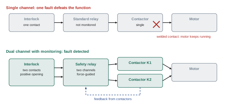
The whole chain matters. A safety-rated light curtain wired into an ordinary programmable controller that switches a single contactor is not a reliable safety function, however good the curtain is. Reliability depends on the weakest part and on how the parts are arranged.
How the standards express reliability
CSA Z432:23 refers to two international standards for safety-related control systems: ISO 13849-1, which uses performance levels (PL a to PL e), and IEC 62061, which uses safety integrity levels (SIL 1 to SIL 3). Most machine builders use ISO 13849-1. The required level for each safety function comes from the risk assessment, as Lesson 4 showed.
ISO 13849-1 is now in its 2023 edition and IEC 62061 in its 2021 edition. Both measure reliability as the average probability of a dangerous failure per hour, written PFHd. A dangerous failure is one that prevents the safety function from working when it is needed.
| Performance level | Average probability of dangerous failure per hour (PFHd) | Roughly equivalent SIL (IEC 62061) |
|---|---|---|
| PL a | 10⁻⁵ to less than 10⁻⁴ | No equivalent |
| PL b | 3 × 10⁻⁶ to less than 10⁻⁵ | SIL 1 |
| PL c | 10⁻⁶ to less than 3 × 10⁻⁶ | SIL 1 |
| PL d | 10⁻⁷ to less than 10⁻⁶ | SIL 2 |
| PL e | 10⁻⁸ to less than 10⁻⁷ | SIL 3 |
Worked problem
What does a PFHd mean in practice?
A safety function achieves PFHd = 5 × 10⁻⁸ per hour, which is PL e. The machine runs 6,000 hours a year. Roughly how many dangerous failures would be expected per year? Compare with a design at 5 × 10⁻⁶ per hour, which is PL b.
Show solution
- Expected dangerous failures per year are approximately PFHd times operating hours.
- PL e: \( 5 \times 10^{-8} \times 6{,}000 = 3 \times 10^{-4} \), about one dangerous failure in 3,300 years of operation.
- PL b: \( 5 \times 10^{-6} \times 6{,}000 = 3 \times 10^{-2} \), about one in 33 years.
Answer: The PL e design is about 100 times less likely to fail dangerously. Across a plant with dozens of machines over decades, that difference is significant. This is a simplification: real calculations also consider diagnostics, test intervals and common-cause failures.
Categories: how the system is built
ISO 13849-1 describes five designated architectures, called categories, that set out how the safety-related parts are arranged and how they behave when faults occur.
| Category | Structure | Behaviour when a fault occurs |
|---|---|---|
| B | Single channel using components suited to the application | A single fault can cause loss of the safety function |
| 1 | Single channel using well-tried components and principles | A single fault can still cause loss of the safety function, but it is less likely |
| 2 | Single channel with periodic automatic testing | A fault can cause loss of the function between tests; the test detects it |
| 3 | Two channels (redundant); some faults detected | A single fault does not cause loss of the function; some faults are detected; accumulated undetected faults can |
| 4 | Two channels; faults detected at or before the next demand | A single fault does not cause loss; faults are detected; accumulation is prevented |
Category alone does not determine the performance level. ISO 13849-1 also considers the mean time to dangerous failure of each channel (MTTFd), the diagnostic coverage (DC), which is the fraction of dangerous failures the system detects, and measures against common cause failures (CCF), such as a single power supply fault or a shared cable that could disable both channels at once. Higher categories with high MTTFd and good diagnostic coverage reach higher performance levels. Most guard interlocks and emergency stops on dangerous machines are designed to Category 3 or 4 to reach PL d or PL e.
Worked problem
Estimating the reliability of an interlock switch
An electromechanical interlock switch has a B10d value of 2,000,000 operations, meaning 10 % of switches are expected to have failed dangerously after that many operations. The guard is opened 20 times an hour, 16 hours a day, 240 days a year. Estimate the switch's MTTFd.
Show solution
- Annual operations: \( n_{op} = 20 \times 16 \times 240 = 76{,}800 \).
- ISO 13849-1 estimates \( \text{MTTF}_d = \dfrac{B_{10d}}{0.1 \times n_{op}} \).
- \( \text{MTTF}_d = \dfrac{2{,}000{,}000}{0.1 \times 76{,}800} \approx 260 \text{ years} \).
- ISO 13849-1 caps the MTTFd used in calculations at 100 years per channel, rated high.
Answer: The switch's MTTFd is about 260 years, treated as 100 years, which is high. But B10d also implies a useful life: \( 0.1 \times B_{10d} / n_{op} \) gives a replacement interval of \( 200{,}000 / 76{,}800 \approx 2.6 \) years at this rate of use, so the switch should be replaced on that schedule. Heavy use wears out electromechanical switches; non-contact coded sensors avoid this.
Well-tried principles and components
Even simple safety functions depend on sound basics. Well-tried safety principles include positive mode actuation, in which a switch's contacts are forced apart mechanically when the guard opens rather than relying on a spring; de-energizing to trip, so that a broken wire or loss of power causes a stop rather than continued running; overdimensioning components; and separating safety circuits from ordinary control wiring. Well-tried components include safety relays with force-guided contacts, which ensure that if one contact welds, its partner cannot change state, allowing the fault to be detected.
Programmable safety and software
Modern machines increasingly use safety-rated programmable controllers and drives with built-in safety functions such as safe torque off, safely limited speed and safe stop monitoring. These allow sophisticated safety functions, such as reduced-speed modes for setup or zone switching for robots, but they introduce software. Safety software must be developed under a disciplined process, protected against unauthorized change, and verified after every modification. An ordinary programmable controller, however reliable for production, should not be used for safety functions unless it is certified for that purpose and the application is validated.
Verification and validation
Designing a safety function is not the end. Verification checks that the design meets its specification, for example by calculating the achieved PL and comparing it with the PLr. Validation checks that the safety function actually works on the real machine as intended, by testing: opening each guard, breaking each curtain, pressing each emergency stop, simulating faults such as a welded contactor, and measuring stopping times. Both should be documented. Validation must be repeated after modifications, repairs that affect safety parts and software changes.
| Check | What it confirms |
|---|---|
| Opening each interlocked guard during operation | The hazardous motion stops and cannot restart while open |
| Closing the guard | The machine does not restart without a separate start command |
| Simulating a welded contactor | The safety relay detects the fault and prevents restart |
| Measuring stopping time | The safety distance is still adequate |
| Pressing each emergency stop | All hazardous motion stops and reset requires deliberate action |
| Reviewing software checksums or version records | The safety program has not been changed without authorization |
What this means for operators and supervisors
You do not need to calculate performance levels to work safely, but you should recognize signs that a safety function may be compromised: a guard that can be opened while the machine keeps running, a machine that restarts by itself when a guard closes, a light curtain that has been moved or has extra beams blanked, an interlock actuator stuck in the switch, jumper wires in a control panel, or a safety relay fault light that keeps coming on. Any of these should be reported immediately and the machine taken out of service until a competent person checks it.
Choosing components
When safety components are chosen, their data sheets matter. A safety-rated interlock switch, light curtain or safety relay lists values such as B10d, PFHd, the maximum category and performance level it can be used in, and its response time. Ordinary components do not, and cannot simply be assumed to be reliable enough. Designers use these values, often with free calculation software from standards bodies such as the German IFA's SISTEMA tool, to calculate the performance level achieved by each safety function and compare it with the PLr from the risk assessment.
Retrofitting older machines raises particular questions. Many machines built before modern standards have single-channel safety circuits with ordinary relays. Upgrading every one at once may not be feasible, so organizations prioritize by risk: machines with the most severe and frequent exposure are upgraded first, often by adding a safety relay, dual-channel interlocks and monitored contactors. A competent person should decide the upgrade path and document the result.
For a supervisor, the practical message is simple: safety circuits are not to be modified, jumpered or reprogrammed by anyone other than authorized, competent people, and every change must be recorded.
Common mistakes
MistakeWiring a safety-rated light curtain into an ordinary production controller.
InsteadThe whole chain, input, logic and output, must meet the required performance level.
MistakeAssuming a single switch and contactor are reliable enough.
InsteadDangerous machines usually need dual-channel, monitored designs to reach PL d or PL e.
MistakeNever replacing electromechanical interlock switches.
InsteadUse B10d data to set replacement intervals for heavily used switches.
MistakeChanging safety software without revalidation.
InsteadControl and verify every change to safety programs and configurations.
MistakeIgnoring repeated safety relay fault indications.
InsteadReport them; they may mean a fault that could disable the safety function.
Summary and key terms
- A safety function has an input, logic and an output, and the whole chain determines reliability.
- ISO 13849-1 uses performance levels from PL a to PL e; IEC 62061 uses SIL 1 to SIL 3.
- Reliability is expressed as the probability of a dangerous failure per hour, PFHd.
- Categories B to 4 describe architecture; MTTFd, diagnostic coverage and common cause measures also matter.
- Well-tried principles such as positive mode actuation and force-guided contacts are fundamental.
- Safety software must be controlled, protected and revalidated after changes.
- Verification checks the design; validation tests the safety function on the real machine.
- Functional safety
- The part of safety that depends on control systems performing safety functions correctly.
- Safety function
- A machine function whose failure would immediately increase the risk.
- Performance level (PL)
- A measure of a safety-related control system's reliability, from a to e.
- Safety integrity level (SIL)
- The IEC 62061 measure of reliability, from 1 to 3 for machinery.
- PFHd
- The average probability of a dangerous failure per hour.
- Category
- A designated architecture in ISO 13849-1 describing structure and fault behaviour.
- MTTFd
- Mean time to dangerous failure of a channel.
- Diagnostic coverage
- The fraction of dangerous failures that the system detects.
- Common cause failure
- A single cause that defeats more than one channel at once.
- Force-guided contacts
- Relay contacts mechanically linked so a welded contact can be detected.
Practice problems
Work each problem on paper first, then reveal the answer to check.
Name the three parts of a safety function.
Show answer
Input, logic and output.
What PFHd range corresponds to PL d?
Show answer
10⁻⁷ to less than 10⁻⁶ per hour.
Which categories tolerate a single fault without losing the safety function?
Show answer
Categories 3 and 4.
What is diagnostic coverage?
Show answer
The fraction of dangerous failures the system detects.
A switch has B10d = 1,000,000 and operates 50,000 times a year. What is its MTTFd?
Show answer
200 years, from 1,000,000 / (0.1 × 50,000); treated as 100 years.
What is positive mode actuation?
Show answer
Contacts forced apart mechanically when the guard opens, not relying on a spring.
Why should a safety circuit de-energize to trip?
Show answer
So that a broken wire or loss of power causes a stop rather than continued running.
What is the difference between verification and validation?
Show answer
Verification checks the design meets the specification; validation tests the function on the real machine.
Give two signs a safety function may be compromised.
Show answer
A guard opens without stopping the machine, the machine restarts when a guard closes, jumpers in a panel, or repeated fault lights.
Why is an ordinary programmable controller unsuitable for safety functions?
Show answer
It is not designed, certified or validated to detect and tolerate faults to the required level.
Lesson quiz · 5 questions
Score 60% or more to complete this lesson.
Create a free account to save your progress, take quizzes and earn a certificate.