
GAS-340 · Lesson 4 of 12 · 21 min
Ignition and flame problems
▶ Video coming soon A video version of this lesson is on the way.
Ignition faults fill more of a winter service board than any other kind. In Rosa's pile were eleven of them from January to March 2026: four igniters, three flame sensors, two intermittent pilot assemblies, a spark module and a burner full of rust scale. Only six of the eleven were the part the customer, or a previous technician, had first suspected. The one she showed Jonah first was a boiler in a duplex on Grosvenor Avenue South that "clicked and clicked and never lit", on which another company had already replaced the spark module. The clicking was a good spark. It just was not reaching any gas.
This lesson covers troubleshooting the three ignition systems found on most appliances, hot surface ignition, direct spark ignition and intermittent pilot ignition, and the flame proving that follows. GAS-220 explained how each works and how flame rectification proves a flame; here the subject is what goes wrong with them, how to tell the failures apart, and how not to be fooled by symptoms that look like ignition faults but are not.
Where in the sequence does it fail?
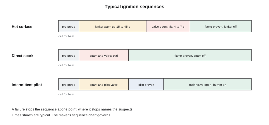
Every ignition fault is diagnosed by watching the sequence and noting exactly where it stops. The control board's sequence for a typical induced-draft furnace is: call for heat, inducer starts, pressure switch closes, igniter or spark energized, gas valve opens, flame is proven within the trial time, the igniter is switched off, the blower starts after a delay. A fault stops the sequence at one point, and that point narrows the suspects.
| Where it stops | What the technician sees | Suspects |
|---|---|---|
| Before the igniter | Inducer runs, no glow or spark | Pressure switch not closing (lesson 5), board, wiring, the igniter itself |
| Igniter on, no gas | Glow or spark, no flame, no gas sound | No voltage at the valve, valve coil open, manual valve shut, no gas supply |
| Gas on, no ignition | Gas valve opens, igniter on, no flame | Igniter too weak or out of position, gas not reaching it, wrong pressure |
| Flame lights, then drops out | Flame for the trial time, then valve closes | Flame not proven: sensor, ground, wiring, polarity, weak flame |
| Flame proven, drops later | Runs, then loses flame | Flame lifting or disturbed: air, pressure, venting, cracked heat exchanger (lesson 8) |
Hot surface ignition
A hot surface igniter, HSI, fails in three ways: it cracks and goes open, it weakens with age and no longer gets hot enough, or it is out of position so that the gas does not reach its hottest part. A cracked igniter is easy: no glow, and an open circuit when its resistance is measured cold with the power off and the plug disconnected. A weak igniter is harder, because it glows but lights the gas late or not at all, and the board locks out after its trials.
The checks are the ones GAS-220 described. The supply voltage at the board's igniter terminals during warm-up should be close to the maker's figure, usually line voltage of about 120 V; low voltage weakens the glow sharply, because the heat produced rises with the square of the voltage. The igniter's cold resistance is compared with the maker's range for that igniter. Silicon carbide igniters typically read somewhere between about 40 and 90 ohms cold, while silicon nitride igniters vary widely by model, so the maker's figure is the only reliable one. The current drawn during warm-up can also be read with a clamp ammeter and compared with the maker's figure.
Worked problem
Is the igniter getting enough power?
A silicon carbide igniter reads 60 ohms cold and is rated by its maker for 120 V. During warm-up, the voltage at its terminals is only 102 V because of a loose neutral connection at the board. Treating its hot resistance as about the same as its cold resistance for a rough comparison, how much does the heating power fall?
Show solution
- Power at the rated voltage:
- \[P = \frac{V^2}{R} = \frac{120^2}{60} = 240 \text{ W}\]
- Power at the low voltage:
- \[P = \frac{102^2}{60} = \frac{10404}{60} \approx 173 \text{ W}\]
- Fraction of rated power:
- \[\frac{173}{240} \approx 0.72\]
- The real hot resistance differs from the cold resistance, so the watts are only a rough guide, but the ratio is set by the voltage alone:
- \[(102 \div 120)^2 = 0.85^2 \approx 0.72\]
Answer: A voltage only 15 in 100 low gives an igniter about 72 in 100 of its rated heating power, enough to make it glow but not always enough to light the gas on a cold morning. Fix the loose neutral before replacing the igniter.
Igniter position matters as much as power. The hot zone must sit where the maker places it, usually just above and in line with a burner port, at a set gap. Universal replacement igniters, which fit many furnaces with an adaptor, are a common cause of delayed or failed ignition because their hot zone does not land where the original's did, as the Corktown case in GAS-220 showed. The maker's replacement part, mounted with the maker's bracket and gasket, avoids that. And an igniter is never touched on its element with bare fingers, because skin oils create hot spots that crack it.
Direct spark and intermittent pilot ignition
Spark ignition fails when the spark is weak, jumps to the wrong place, or does not meet the gas. A weak or missing spark may be a failed module, a cracked electrode insulator, a high-voltage lead that is chafed or wet, or a gap that has grown with wear. A spark that jumps somewhere else, to a burner bracket instead of across the gap, shows up as a spark you can hear but in the wrong place, and the cure is to find and fix the leak path. A good spark that does not light the gas means the gas is not there: the valve is not opening, the pilot or burner orifice is blocked, or the gas pressure is wrong.
Intermittent pilot ignition, IPI, adds a step: the pilot must light and be proven before the main valve opens. A pilot that lights but is not proven, so the main burner never comes on, is usually a flame-sensing problem at the pilot: a small or yellow pilot flame that does not envelop the sensor, a rusty pilot orifice, a cracked sensor insulator, or a poor ground between the pilot burner and the module. The Aberdeen boiler in GAS-220 was a case like this.
The duplex boiler
At the duplex on Grosvenor Avenue South, Rosa watched the sequence on the IPI boiler: call, spark, the pilot valve clicked open, spark continued for the full trial, no pilot flame, lockout. The new spark module was sparking strongly across the right gap. With her manometer on the boiler's inlet tap she read a normal inlet pressure, and with a second reading on the pilot tubing fitting during the trial she read almost nothing. Gas was reaching the valve but not the pilot.
She shut off the gas, removed the pilot tubing and found the pilot orifice packed with a fine black powder. The boiler's gas connection had no sediment trap, and the utility had replaced the street service the previous autumn; debris from the new service had travelled down the house line, through the valve's inlet screen, which was partly torn, and into the tiny pilot orifice. Rosa cleaned the line, fitted a new pilot orifice and a new combination valve because of the torn screen, added a sediment trap at the boiler's connection as the code requires, and checked the pilot flame: a steady blue flame enveloping the sensor, with a signal of 2.4 µA. The spark module the other company had fitted had never been at fault.
Flame proving problems
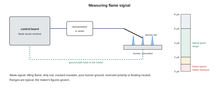
When the flame lights and then the valve closes at the end of the trial time, the flame was there but the control did not prove it. Flame rectification, as GAS-220 explained, depends on a flame in good contact with the sensor rod, a flame-to-ground path through the burner, a clean rod and insulator, correct polarity and a good ground at the board. Each one is checked in turn:
- Read the flame signal. A microammeter in series with the sensor lead, or the board's own diagnostic display, gives a reading in microamps. Typical good readings are about 2 to 6 µA on many furnaces, with a minimum from the maker that is often around 0.5 to 1 µA. The maker's figures govern.
- Look at the flame. A flame that is lifting, yellow, ragged or not touching the rod gives a weak signal however clean the rod is.
- Check the rod and insulator. Clean the rod with a fine abrasive pad, not emery cloth, and look for a cracked porcelain insulator that leaks the signal to ground.
- Check the ground path. The burner must be grounded to the board. Corroded burner mounts, painted brackets or a loose ground wire weaken the circuit.
- Check polarity and the neutral. Many boards need correct polarity on their line voltage supply and a neutral bonded to ground. Reversed polarity or a floating neutral, as in the Beasley case in GAS-220, can stop flame proving altogether.
Ignition faults that are not ignition faults
Some of the hardest ignition calls turn out to have nothing to do with the ignition system. A technician who has watched the sequence carefully will often see the clue: the igniter and the gas valve do their jobs, and something else stops the flame. The common impostors are worth knowing:
- Gas pressure. A manifold pressure well below the plate makes a weak flame that may not carry across the burners to the sensor; one well above it can blow the flame off the ports. Lesson 3 covers the readings.
- Wrong or blocked orifices. A furnace converted to propane and back, or with a spider nest in an orifice, lights badly at one end of the burner rack.
- Venting and combustion air. A restricted vent or a depressurized room changes the flame and the flame signal, especially on cold or windy days. A flame that is fine with the door of the furnace room open and poor with it closed is short of combustion air.
- Delayed ignition. A burner that lights with a bang has gas collecting before it lights: a mispositioned igniter, rusty crossover ports that stop the flame carrying across, or low pressure. Delayed ignition can crack heat exchangers and blow vent connectors apart, and it is never left unfixed.
- A cracked heat exchanger. A flame that is proven and then disturbed when the blower starts, as in GAS-220's Rosedale case, is a heat exchanger problem first, as lesson 8 explains.
The rule from lesson 2 applies: when the obvious part tests good, look at what the flame is telling you. On the duplex boiler, the spark was good, so the question became where the gas was.
| Symptom | Look first at |
|---|---|
| Igniter glows, valve opens, no flame | Igniter voltage and position; gas pressure at the valve outlet |
| Spark good, pilot never lights | Pilot gas: tubing, orifice, valve pilot outlet |
| Lights with a bang | Igniter position, crossover ports, pressure |
| Lights, drops out after the trial | Flame signal, ground, polarity, flame shape |
| Runs, drops out when the blower starts | Heat exchanger (lesson 8) |
| Drops out on windy or cold days | Venting, terminations, combustion air |
Replacing ignition parts properly
When an ignition part has been proved faulty, it is replaced with the maker's part or an approved replacement listed for that appliance, mounted with the maker's bracket and gasket, and wired exactly as the original was. A hot surface igniter's leads are routed away from hot surfaces and secured. A spark electrode's gap is set to the maker's dimension with a gauge. An intermittent pilot assembly is replaced as a kit where the maker offers one, because the pilot burner, electrode, sensor and orifice are matched. After replacement, the technician watches several complete sequences, measures the flame signal, checks that ignition is smooth and quiet with no delay, and records the readings. A replaced part that lights the burner once has not been verified; one that lights it smoothly ten times in a row, on low and high fire, has.
Common mistakes
MistakeReplacing the igniter or module before watching where the sequence stops.
InsteadWatch the sequence; the stopping point names the suspects.
MistakeCondemning an igniter that glows without checking the voltage at it.
InsteadRead the voltage during warm-up; a small drop costs a lot of heat.
MistakeFitting a universal igniter where the hot zone does not meet the gas.
InsteadUse the maker's part, bracket and position.
MistakeTouching an igniter element with bare fingers.
InsteadHandle it by its base.
MistakeCleaning a flame sensor and leaving without measuring the signal.
InsteadMeasure the flame signal before and after.
MistakeAssuming a good spark means a good ignition system.
InsteadCheck that gas actually reaches the spark: pilot pressure, orifice, valve.
Summary and key terms
- Ignition faults are diagnosed by watching the sequence and noting where it stops: before the igniter, igniter on with no gas, gas with no ignition, flame lost at the end of the trial, or flame lost later.
- Hot surface igniters fail open, weaken or are mispositioned; check the voltage during warm-up (heat rises with the square of the voltage), the cold resistance against the maker's range and the position.
- Spark systems fail from weak sparks, sparks to the wrong place, or no gas at a good spark.
- Intermittent pilots fail mostly at the pilot flame and its sensing.
- Flame proving needs a good flame on a clean rod, a sound insulator, a grounded burner and correct polarity, and is checked by measuring microamps against the maker's figures.
- Hot surface igniter
- A ceramic element heated by electric current until it is hot enough to light gas.
- Trial for ignition
- The time the control allows for flame to be proven after the gas valve opens.
- Flame signal
- The small direct current, in microamps, that flows through a flame by rectification and proves it to the control.
- Sediment trap
- A capped tee or drip leg at an appliance connection that catches debris before it reaches the valve.
- Universal igniter
- A replacement igniter made to fit many appliances, often with an adaptor.
- Floating neutral
- A neutral conductor not properly bonded to ground, which can upset flame rectification.
Practice problems
Work each problem on paper first, then reveal the answer to check.
A furnace's igniter glows, the gas valve opens, and there is no flame. Name two suspects.
Show answer
A weak or mispositioned igniter, gas not reaching it, or wrong gas pressure.
Why does a small voltage drop matter so much to a hot surface igniter?
Show answer
Its heat rises with the square of the voltage, so 15 in 100 low gives only about 72 in 100 of the heat.
What was wrong with the duplex boiler that clicked and never lit?
Show answer
Its pilot orifice was blocked with debris from a new street service; the valve's inlet screen was torn and there was no sediment trap.
How is flame signal measured?
Show answer
With a microammeter in series with the flame sensor lead, or from the board's diagnostic display.
Name three things that weaken a flame signal.
Show answer
A lifting flame, a dirty rod, a cracked insulator, a poor burner ground or reversed polarity.
Lesson quiz · 5 questions
Score 60% or more to complete this lesson.
Create a free account to save your progress, take quizzes and earn a certificate.