
GAS-340 · Lesson 2 of 12 · 22 min
A systematic troubleshooting method
▶ Video coming soon A video version of this lesson is on the way.
The second work order in Rosa's pile was from February 2026: a townhouse on Upper Paradise Road where the furnace had quit three times in two weeks, each time early in the morning, and each time worked again after the owner switched it off and on. Two other companies had been out. One had cleaned the flame sensor, the other had replaced the thermostat. Neither had found anything wrong, because each time they arrived the furnace was running. "Two smart people looked at this," Rosa told Jonah, "and both of them went straight to the part they suspected. Neither of them asked the furnace what it had been doing." The furnace, it turned out, had been keeping a record the whole time.
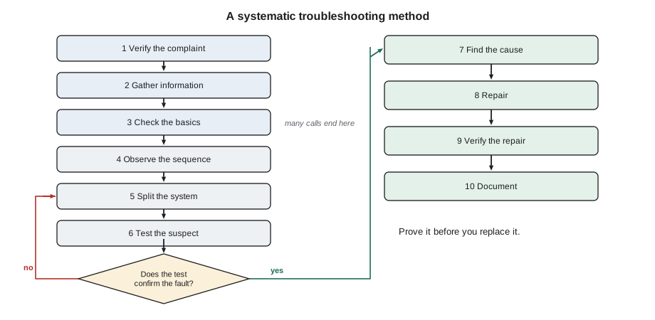
This lesson sets out a method for troubleshooting that works on any gas appliance, from a water heater to a burner management system. It is the same ten-step idea GAS-130 and GAS-220 introduced for electrical and control faults, widened to cover the whole appliance: verify the complaint, gather information, check the basics, observe the sequence, split the system, test the suspect, repair the cause, verify the repair and document it. The method is slower than guessing on the first call of the day and much faster by the end of the week.
Why method beats guessing
Experienced technicians are often good guessers, and guessing is fast when it is right. The trouble is what happens when it is wrong. A part is replaced, the appliance runs, the technician leaves, and the fault comes back the next cold morning. The customer has paid for a part they did not need and still has the problem. Worse, the real cause may be a hazard: a cracked heat exchanger mistaken for a dirty flame sensor, a blocked vent mistaken for a bad pressure switch. Part-swapping also hides evidence, because the old part goes in the bin before anyone has tested it.
A method does not forbid experience. It tells the technician where to use it: in deciding which part of the system to test first, not in skipping the test. The rule Rosa gave Jonah was short: "Prove it before you replace it."
The steps
- 1. Verify the complaint. See the fault for yourself if you can. "No heat" may mean no heat at all, heat in some rooms, heat that is too cool, or a thermostat set to cool. If the fault is intermittent and not happening now, the verification is the customer's description plus whatever the appliance has recorded.
- 2. Gather information. Ask the questions from lesson 1, read the rating plate, find the installation and service manuals (the maker's website, a QR code on the appliance or the manual in a pouch inside the door), read the fault history and any error codes, and look at the service record.
- 3. Check the basics. Power at the appliance, gas at the appliance, a call for heat or hot water, the switch and valve positions, filters, condensate drains, vent and intake terminations. A surprising number of calls end here.
- 4. Observe the sequence. Watch the appliance run through its sequence of operation, from call to ignition to steady run to shutdown, and note exactly where it departs from what the manual says should happen. The sequence charts in GAS-220 and GAS-310 are the map.
- 5. Split the system. Decide which half of the system the fault is in, then which half of that half, until it is narrowed to one component or connection. The next section explains how.
- 6. Test the suspect. Measure the suspected component with the right instrument and compare the reading with the maker's specification: voltage across a switch, resistance of an igniter, microamps from a flame sensor, pressure at a switch.
- 7. Find the cause, not just the failed part. A burnt-out igniter may have failed because it was touched during installation or because the supply voltage is high. A tripped limit may have tripped because the filter is blocked. Ask why the part failed.
- 8. Repair. Fix the cause and replace the failed part with the maker's part or an approved equivalent.
- 9. Verify the repair. Run the appliance through several complete cycles, take the readings that prove it is working safely (pressures, temperature rise, combustion, flame signal, safety control tests) and, for an intermittent fault, recreate the condition that caused it if you can.
- 10. Document. Record what was found, the readings as found and as left, what was done and what the customer was told, as lesson 10 describes.
Splitting the system
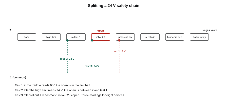
Splitting is the most powerful idea in troubleshooting. Instead of testing every part in turn, the technician tests at a point near the middle of the suspect area. If the signal, pressure or voltage is right there, the fault is downstream; if not, it is upstream. Each test removes half of the possibilities. On a safety circuit with eight switches in series, testing one switch at a time from the start could take eight tests; splitting takes at most three.
The same idea works on every kind of system. On a gas train, reading the pressure halfway along tells whether a low manifold pressure is caused by the supply or by the appliance's own valve. On a venting problem, reading the draft at the appliance and at the chimney base tells whether a restriction is in the connector or in the chimney. On a 24-volt circuit, reading voltage from one point to a common reference, as GAS-130 described, tells which side of a point the open is on.
Worked problem
How many tests does splitting take?
A safety chain has 8 switches in series, and one of them is open. How many voltage readings does it take, at most, to find the open switch by testing one switch after another from the start, and by splitting the chain in half each time?
Show solution
- One after another, the open switch could be the last one, so at most:
- \[8 \text{ tests (7 if the last is assumed)}\]
- Splitting halves the possibilities with each reading:
- \[8 \to 4 \to 2 \to 1\]
- That is three readings, because:
- \[2^3 = 8\]
- For a chain of 16 devices, splitting would take four readings, since:
- \[2^4 = 16\]
Answer: At most 8 readings in order, but only 3 by splitting. The saving grows with the size of the system, which is why splitting is the habit to build.
Intermittent faults
Intermittent faults are the hardest calls because the evidence is usually gone when the technician arrives. The method still works, but steps 1 and 2 carry more weight:
- Read the fault history. Most modern control boards store their last several faults, often with a count and sometimes with the time since each occurred. A board that shows five pressure switch faults and no flame faults has told the technician where to look.
- Ask about the pattern. Cold mornings, windy days, after a long run, when the dryer is on, after a power cut. The pattern is a clue to the cause: cold and wind point to venting and condensate, long runs to overheating, the dryer to depressurization.
- Recreate the condition. Run the appliance at high fire for a long time, switch on every exhaust fan in the house, block the filter partly to test the limit, or wait for the cold morning and come back early.
- Leave a recorder. A pressure logger on the pressure switch line, a temperature logger in the supply plenum, or a data logger on a boiler control can catch the fault when nobody is watching. GAS-220's Kowalczyk case was solved with a logged pressure reading.
When a fault cannot be found on the first visit, the technician says so honestly, explains what was tested and ruled out, and agrees a plan with the customer: a logger, a return visit, or a call the moment it happens again so that the technician can see the fault live.
What the townhouse furnace had recorded
At the townhouse on Upper Paradise Road, Rosa started with steps 1 and 2. The furnace was running when she arrived. The owner described the pattern: the house was cold when he got up, the furnace's light was flashing, and switching it off and on fixed it. Rosa found the maker's manual on her phone and read the fault history from the control board's display. It showed seven lockouts in two weeks, all of them for "flame lost three times during one call", and no pressure switch or limit faults.
Flame loss with a running inducer and a closed pressure switch narrowed the suspects to the flame circuit and the burner, which is what the first company had guessed. But the first company had cleaned the sensor without measuring the signal. Rosa measured it: 2.8 µA at low fire, against a typical good range of about 2 to 6 µA, and the maker's minimum of 0.8 µA. That was adequate, but she watched it through a full cycle. When the furnace shifted from low fire to high fire and the inducer speeded up, the signal dropped to 0.6 µA for a few seconds and the flame visibly lifted off the sensor. That pointed away from the sensor and toward the flame.
At high fire the manifold pressure was correct, but the combustion analyzer showed high oxygen and the flame at the sensor end of the burner was lifting. The burner's air shutter on that end had been knocked open, probably when the flame sensor was cleaned, and too much primary air at high fire lifted the flame off the sensor rod on cold mornings, when the dense cold air made the effect worse. Rosa set the shutter to the maker's position, verified the flame signal at 3.4 µA through ten cycles, low and high fire, and left a note to call her at once if the light flashed again. It did not.
| Step | What Rosa did at the townhouse |
|---|---|
| Verify | Owner's description: cold mornings, flashing light, reset fixes it |
| Gather | Manual on her phone; fault history: 7 lockouts, all flame lost |
| Basics | Power, gas, filter, condensate, terminations all good |
| Sequence | Watched low fire, then the shift to high fire |
| Split | Inducer and pressure switch good; fault in flame circuit or burner |
| Test | Flame signal 2.8 µA at low fire, 0.6 µA at high fire; flame lifting |
| Cause | Air shutter knocked open; excess primary air at high fire |
| Repair | Shutter reset to the maker's position |
| Verify | 3.4 µA through ten cycles at both firing rates |
| Document | Readings, cause, note to the owner |
Tools of the method
The method depends on instruments, and the technician's kit for service is larger than for installation. Bayline's service technicians carry a digital multimeter with a microamp range or a clamp meter that reads microamps, a clamp ammeter, a digital manometer with two ports, a combustion analyzer, a personal CO monitor, a combustible gas detector, a thermometer with two probes, an inspection camera, and a phone or tablet with the makers' manuals. Each instrument is checked before use: the combustion analyzer zeroed in fresh air and calibrated on the maker's schedule, the manometer zeroed with both ports open, the meter tested on a known source. A reading from an instrument nobody has checked is only a guess with a number on it.
Using the manual and the sequence chart
Every appliance's installation and service manual contains the information the method depends on: the sequence of operation, the wiring and ladder diagrams, the fault code chart, the gas pressures and the safety control settings, and usually a troubleshooting chart of the maker's own. Bayline technicians find the manual before they start testing, not after they are stuck. Most makers publish their manuals on their websites, many appliances carry a QR code or a model number that leads straight to them, and the maker's technical support line can help with an unusual fault.
The maker's troubleshooting chart is a good guide but not a substitute for the method. It usually assumes the basics are right and the installation is correct, and it lists the likely causes of each code in order. A technician who follows it blindly can replace three parts on a furnace whose real fault is a blocked termination. A technician who has done steps 1 to 4 first, and knows where the sequence stops, uses the chart to choose what to test, and tests it.
Knowing when to stop and ask
Part of a systematic method is knowing its limits. A technician who has worked through the steps and cannot find the fault, or who is out of their depth on unfamiliar equipment, stops and asks: a senior technician at the shop, the maker's support line, or the office to send someone with more experience of that equipment. Asking is not a failure. Guessing on a gas appliance is. Bayline's apprentices are told that the only bad question is the one not asked before a part is ordered or an appliance is left running.
Common mistakes
MistakeReplacing the part you suspect without measuring it.
InsteadProve it before you replace it.
MistakeStarting to test before checking power, gas, call, filter, drain and terminations.
InsteadCheck the basics first; many calls end there.
MistakeTesting every part in order.
InsteadSplit the system and halve the possibilities with each test.
MistakeIgnoring the control board's fault history.
InsteadRead it first on any intermittent fault.
MistakeReplacing a failed part without asking why it failed.
InsteadFind the cause, or the new part will fail too.
MistakeLeaving after one good cycle.
InsteadVerify through several complete cycles and the condition that caused the fault.
Summary and key terms
- A systematic method works on any gas appliance: verify the complaint, gather information, check the basics, observe the sequence, split the system, test the suspect, find the cause, repair, verify and document.
- It is slower than guessing on one call and much faster over a season, and it protects customers from hidden hazards and unneeded parts.
- Splitting tests near the middle of the suspect area and removes half the possibilities each time, so eight devices need at most three readings.
- Intermittent faults rely on the fault history, the pattern of the fault, recreating the condition and loggers.
- Instruments are checked before they are trusted.
- Sequence of operation
- The order of events an appliance goes through from a call to shutdown, set out in its manual.
- Splitting
- Testing near the middle of the suspect part of a system to decide which half holds the fault.
- Fault history
- The list of recent faults stored by a control board, often with counts.
- Intermittent fault
- A fault that comes and goes and may not be present when the technician arrives.
- Data logger
- An instrument that records readings over time so a fault can be caught when nobody is watching.
- Part-swapping
- Replacing parts on suspicion without testing them.
Practice problems
Work each problem on paper first, then reveal the answer to check.
List the ten steps of the method in order.
Show answer
Verify, gather information, check the basics, observe the sequence, split, test, find the cause, repair, verify, document.
How many readings does splitting need, at most, to find one open switch among 16?
Show answer
Four, because 2 × 2 × 2 × 2 = 16.
What did the townhouse furnace's fault history show?
Show answer
Seven lockouts, all for flame lost, and no pressure switch or limit faults.
Why is it important to ask why a part failed?
Show answer
The cause may still be there and will destroy the new part, or may be a hazard.
Name two ways to catch an intermittent fault.
Show answer
Read the fault history, recreate the condition, or leave a data logger.
Lesson quiz · 5 questions
Score 60% or more to complete this lesson.
Create a free account to save your progress, take quizzes and earn a certificate.