
GAS-330 · Lesson 3 of 12 · 21 min
Service, line and appliance regulators
▶ Video coming soon A video version of this lesson is on the way.
On Monday, September 21, Northvale Homes asked Bayline to check a block of twelve townhouses on Fruitland Road in Stoney Creek before the utility turned the gas on. Northvale had built the block with a single elevated-pressure system: one utility meter set per unit on the end wall at 14 kPa (2 psig), a short run of steel into each unit, a line regulator in each utility room, and flexible tubing from there to the furnace, water heater, range and dryer. The builder's own gas sub had installed it, and Northvale's site supervisor, who had been caught out by a failed inspection on another job, wanted a second pair of eyes. Grant and Ayesha spent the day going unit by unit with the drawings, a gauge, a manometer and a flashlight.
This lesson describes the three places a regulator sits in a gas system, and what each one does: the utility's service regulator at the meter, the line pressure regulators that reduce an elevated building pressure, and the appliance regulators that set the pressure at the burners. It covers how each is certified, installed, set and checked, and how they work together in series.
Three regulators in series
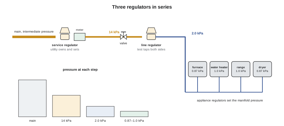
Gas reaching a burner in an elevated-pressure building has usually passed through three regulators, each taking a step down. The utility's service regulator reduces the main pressure to the delivery pressure. A line pressure regulator reduces the delivery pressure to what the appliances need at their inlets. Each appliance's own appliance regulator, often built into its combination gas valve, reduces that to the manifold pressure its burner was set up for. Each regulator works only if the one before it gives it enough inlet pressure and does not give it more than it can take.
The service regulator
The service regulator belongs to the utility. It is part of the meter set, it is sized and set by the utility for the delivery pressure it has agreed with the customer, and only the utility adjusts, repairs or replaces it. Most service regulators have built-in overpressure protection, usually an internal relief valve that vents gas through the regulator's vent if the outlet pressure rises too far, and some larger sets have a second regulator acting as a monitor. A gas technician reads the delivery pressure at the meter outlet but never touches the service regulator's adjustment or seal. If the delivery pressure is wrong, the utility is called.
What the technician does own is everything around it that could make it fail: building additions that enclose the meter, decks and stairs built over the regulator vent, snow and ice falling from a roof onto it, landscaping that buries it, and vehicles that could hit it. Enbridge publishes clearances around its meter sets and regulator vents, and a technician who sees a meter set in trouble reports it.
Line pressure regulators
A line pressure regulator sits in the customer's piping and reduces an elevated pressure, typically 14 or 35 kPa (2 or 5 psig), to the pressure the appliances need. Line regulators for building use are certified to the joint standard CSA 6.22/ANSI Z21.80, which divides them into classes by their maximum outlet pressure: a Class I line regulator has an outlet of no more than 3.5 kPa (0.5 psig) and is used to feed appliances directly; a Class II line regulator has an outlet of up to 14 kPa (2 psig) and is used to step a 35 kPa (5 psig) system down to a 14 kPa (2 psig) distribution system. Each certified regulator is marked with its maximum inlet pressure, and it must never be installed where the inlet can exceed that marking.
Some line regulators include an overpressure protection device, OPD: a second element that limits the outlet pressure if the main regulator fails. Whether an OPD is required, and what kind, is the subject of lesson 5; here it is enough to know that the regulator's tag tells you whether it has one, and that a regulator labelled with an OPD is installed and tested as a single listed assembly.
Installation rules for line regulators follow both codes and the maker's instructions, and they are where the Northvale block was most likely to go wrong:
- Access. The regulator must be accessible for service, adjustment and replacement. It is not buried in a finished ceiling or wall.
- A shutoff valve upstream. A manual shutoff valve sits immediately upstream of the regulator so it can be isolated.
- Test points. A capped tee or test port upstream and another downstream let the inlet and outlet pressures be read. The maker's instructions and the code say where; downstream taps are usually a few pipe diameters past the regulator.
- A union or other means of removal, close to the regulator where it is connected to rigid pipe.
- Orientation. Most line regulators must be installed with the diaphragm housing in a particular position, often upright in horizontal pipe, so that the diaphragm works freely and the vent can breathe. The flow arrow on the body must point downstream.
- The vent, covered in lesson 4: piped outdoors or fitted with a listed vent limiter where the regulator is certified for one.
- Sizing. Chosen from the maker's table for the actual loads, as lesson 2 explained.
Setting and checking a line regulator
A line regulator is set with gas flowing, because its set point is defined at flow. The technician connects a manometer or low-range gauge at the downstream tap, lights one or more appliances so that some gas flows, removes the regulator's cap and turns the adjusting screw, clockwise to raise the pressure, until the outlet reads the design pressure. Then the cap goes back on, because on many regulators the cap is part of the vent path or the spring housing seal. Finally the technician checks the two ends of the flow curve: lockup with everything off, and the outlet with every appliance on that regulator firing at once. A good installation shows a small rise at lockup that holds steady and a small drop at full load.
Worked problem
Is there enough pressure at the appliances?
Northvale's line regulators are set to 2.0 kPa. The tubing from each regulator to its appliances was sized for a drop of 0.5 kPa at full load. The furnace's plate gives a minimum inlet pressure of 1.12 kPa and a maximum of 3.5 kPa. Check both limits.
Show solution
- At full load the furnace sees:
- \[2.0 - 0.5 = 1.5 \text{ kPa} \geq 1.12 \text{ kPa}\]
- At no flow, with a lockup of about 15 in 100:
- \[2.0 \times 1.15 = 2.3 \text{ kPa} \leq 3.5 \text{ kPa}\]
Answer: The set point sits comfortably between the appliances' minimum and maximum inlet pressures. A higher set point would leave more margin at full load but less at lockup; the designer chose 2.0 kPa to keep both.
Appliance regulators
An appliance regulator sets the pressure at the burner manifold, the pressure the burner orifices were sized for. On most furnaces, boilers and water heaters it is built into the combination gas valve, and it is adjusted under a cap on the valve while reading the manifold pressure at the valve's outlet tap. On commercial cooking equipment, unit heaters and larger burners it is often a separate appliance regulator, certified to the appliance regulator standard, mounted at the appliance inlet. Appliance regulators are built for low inlet pressures, commonly a maximum of 3.5 kPa (0.5 psig), which is why they must be protected by a line regulator on any elevated-pressure system. The manifold pressure is set to the appliance's rating plate, typically about 0.87 kPa (3.5 in. w.c.) for natural gas furnaces, and confirmed by clocking the meter, as lesson 6 explains.
Where an appliance regulator is part of the appliance's certification, it stays: a technician does not remove a regulator from a certified appliance because the building's line regulator seems to make it unnecessary. Each regulator in the series does its own job.
| Regulator | Owned and set by | Typical outlet | Key checks |
|---|---|---|---|
| Service regulator | The utility | 1.74, 14 or 35 kPa | Read at meter outlet; vent clear; report problems |
| Line regulator, Class II | Gas technician | Up to 14 kPa | Max inlet marking; OPD; access; test taps |
| Line regulator, Class I | Gas technician | Up to 3.5 kPa | Set at flow; lockup and full-load readings |
| Appliance regulator | Gas technician | Manifold, e.g. 0.87 kPa | Set to rating plate; confirm by clocking |
What Grant and Ayesha found at Northvale
Nine of the twelve units were as drawn. In unit 4 the line regulator had been installed in the utility room ceiling before the drywall went up and was now behind a finished ceiling with no access panel. In unit 9 the regulator was installed upside down, with its diaphragm housing hanging below the pipe, where the maker's instructions said it must be upright; its vent would also have collected moisture. In unit 11 there was no test tee downstream of the regulator, so its outlet pressure could not be read without breaking a joint.
With the utility's meters still locked off, they could not set the regulators on gas, but they could do everything else. They wrote up the three faults with photographs and the maker's installation sheet for the regulator model, and confirmed that every regulator tag showed a maximum inlet pressure of 35 kPa (5 psig), a Class I outlet, and an integral OPD, so the system needed no separate overpressure device. They also checked that each regulator's vent was either piped outdoors or fitted with the vent limiter the regulator was certified with, which lesson 4 discusses.
Northvale's sub fixed the three units that week: an access panel for unit 4, a reinstalled regulator in unit 9 and a new tee in unit 11. On Monday, September 28, after the utility unlocked the meters, Ayesha went back and set each regulator to 2.0 kPa with the furnace firing, then read lockup and full-load outlet pressures. Lockup ran from 2.2 to 2.3 kPa and the full-load readings from 1.8 to 1.9 kPa at the regulator. She recorded all twenty-four readings on the commissioning sheet for the inspector.
Troubleshooting a line regulator
When appliances on an elevated-pressure system misbehave, the line regulator is one of the first suspects, but it is often blamed for faults elsewhere. A systematic check separates them. The technician reads three pressures: the inlet to the regulator, its outlet, and the appliance's own inlet or manifold, each at no flow and at full flow. The pattern of the readings points to the cause.
| What the readings show | Likely cause |
|---|---|
| Inlet low at full flow, outlet low | Supply problem: undersized main, meter or service, or a closed or partly closed valve upstream |
| Inlet good, outlet droops badly at full flow | Regulator too small for the load, wrong spring, or a restricted strainer just upstream |
| Inlet good, outlet good, appliance inlet low | Undersized piping or connector between regulator and appliance |
| Outlet swings up and down | Restricted vent, oversized regulator, or a sensing line in the wrong place |
| Outlet creeps up at no flow | Regulator leaking through: debris on the seat or a worn disc |
| Outlet at inlet pressure, OPD tripped | Regulator failed open; find out why before resetting |
Two further checks help. A strainer upstream of the regulator can clog with scale on a new system and starve the regulator at high flow; reading the pressure on both sides of the strainer at full flow shows it. And a regulator's spring can be the wrong one for its set point: if the adjusting screw is wound almost fully in or almost fully out, the spring is near the end of its range, and the regulator will control poorly. The spring's colour or part number on the tag, checked against the maker's spring chart, settles it.
When the cause is the regulator itself, the repair is the one the maker allows. Some line regulators can be fitted with a new seat and disc or a new diaphragm from a maker's kit; many small ones cannot be repaired in the field and are replaced. A regulator with an integral OPD is a listed assembly, and its parts are replaced only with the maker's parts, in the way the maker describes, followed by a trip test of the OPD. After any repair or replacement, the regulator is set at flow and checked at lockup and full load, as for a new installation.
Common mistakes
MistakeAdjusting the utility's service regulator.
InsteadNever touch it; call the utility if the delivery pressure is wrong.
MistakeInstalling a line regulator where its inlet can exceed its marked maximum.
InsteadCheck the tag against the highest pressure the supply can deliver.
MistakeBurying a line regulator behind a finished wall or ceiling.
InsteadKeep it accessible for service, adjustment and replacement.
MistakeMounting a regulator in any position that fits.
InsteadFollow the maker's orientation and the flow arrow.
MistakeSetting a line regulator with no gas flowing.
InsteadSet it at flow, then check lockup and full-load pressures.
MistakeRemoving an appliance's own regulator because a line regulator is upstream.
InsteadLeave certified appliance regulators in place; each does its own job.
Summary and key terms
- Gas in an elevated-pressure building usually passes three regulators in series.
- The utility's service regulator sets the delivery pressure and is owned, set and repaired only by the utility; it usually carries its own relief.
- Line pressure regulators, certified to CSA 6.22/ANSI Z21.80, reduce 14 or 35 kPa to appliance pressures: Class I outlets go up to 3.5 kPa and Class II up to 14 kPa, and each is marked with its maximum inlet pressure.
- They need access, an upstream shutoff valve, upstream and downstream test taps, a means of removal, the maker's orientation and a proper vent, and they are set at flow and checked at lockup and full load.
- Appliance regulators, often in combination valves, set the manifold pressure to the rating plate and are built for low inlet pressures.
- Service regulator
- The utility's regulator at the meter set that sets the delivery pressure.
- Line pressure regulator
- A regulator in the customer piping that reduces elevated pressure for appliances.
- Class I line regulator
- A line regulator with an outlet pressure of no more than 3.5 kPa (0.5 psig).
- Class II line regulator
- A line regulator with an outlet pressure of up to 14 kPa (2 psig).
- Appliance regulator
- A regulator that sets an appliance's manifold pressure, often inside its combination gas valve.
- Combination gas valve
- An appliance valve combining manual shutoff, safety shutoff, regulator and often pilot control.
- Test tap
- A plugged port or tee used to read pressure upstream or downstream of a regulator.
Practice problems
Work each problem on paper first, then reveal the answer to check.
Who may adjust the service regulator at a meter set?
Show answer
Only the utility.
What is the difference between a Class I and a Class II line regulator?
Show answer
Class I outlets go up to 3.5 kPa; Class II outlets go up to 14 kPa.
Name four installation requirements for a line regulator.
Show answer
Access, an upstream shutoff valve, upstream and downstream test taps, and the maker's orientation; also a means of removal and a proper vent.
Why is a line regulator set with gas flowing?
Show answer
Its set point is defined at flow; at no flow it rises to lockup.
What was wrong with the regulator in Northvale's unit 9?
Show answer
It was installed upside down, against the maker's orientation.
Lesson quiz · 5 questions
Score 60% or more to complete this lesson.
Create a free account to save your progress, take quizzes and earn a certificate.