
GAS-330 · Lesson 2 of 12 · 23 min
How regulators work
▶ Video coming soon A video version of this lesson is on the way.
On Friday, September 18, Romano's Pizzeria on Upper James Street called Bayline with a complaint that sounded like a cooking problem. A month earlier the owner, Frank Romano, had added a second deck oven, and a plumbing contractor had run the gas line to it. Since then, on busy Friday nights, the new oven took forever to recover after the door was opened, the old conveyor oven's flames turned soft and yellow-tipped, and the range burners would not hold a high flame when everything was on. At four in the afternoon, with the kitchen quiet, everything looked fine. Maureen sent Grant and Ayesha for the dinner rush. "Bring the gauges and a manometer," she said, "and read the pressure after the regulator with nothing on, then with everything on. I'll bet the story's in the difference."
This lesson explains how a gas pressure regulator works: its three working parts, how it holds a set outlet pressure, why the outlet pressure falls as flow rises, what lockup is, and how a regulator is chosen for the flow and pressures it must handle. Lesson 3 then sorts regulators by where they are used, and lessons 4 and 5 cover their vents and what happens when they fail.
What a regulator does
A pressure regulator takes gas at a higher, often varying, inlet pressure and delivers it at a lower, steady outlet pressure, whatever the flow the appliances downstream demand, from nothing to their full input. It does this without any outside power: the gas itself supplies the energy. A good way to picture it is a valve that is being continuously opened and closed by a hand that feels the outlet pressure: if the outlet pressure starts to fall because the appliances are taking more gas, the hand opens the valve further; if the outlet pressure rises because they are taking less, the hand closes it.
Every self-operated regulator has three elements that do this job:
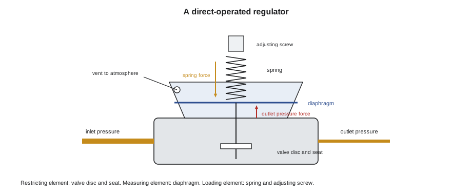
- The restricting element is the valve: a valve disc or plug that moves toward or away from an orifice, the seat, to throttle the gas.
- The measuring element is the diaphragm: a flexible disc with outlet pressure on one side and atmospheric pressure, through the vent, on the other. It feels the outlet pressure and moves the valve through a linkage or stem.
- The loading element is the spring: it pushes on the diaphragm in the direction that opens the valve. Its force, set by an adjusting screw, decides the outlet pressure the regulator will hold.
In balance, the spring's force pushing the diaphragm one way equals the outlet pressure's force pushing it the other. If outlet pressure falls, the spring wins, the diaphragm moves, and the valve opens further; if outlet pressure rises, the gas wins and the valve closes. The set point is the outlet pressure at which the two balance, and turning the adjusting screw to compress the spring raises it. Because the spring pushes the valve open, a regulator of this kind is normally open: lying on the bench, with no pressure under its diaphragm, its valve is wide open. That fact explains why a failed diaphragm or a blocked vent can send full inlet pressure downstream, as lesson 5 explains.
Droop: why outlet pressure falls with flow
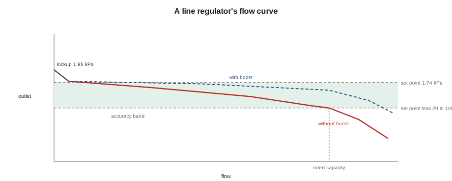
A spring's force changes as it stretches. To pass more gas, the valve must open further, so the diaphragm must move further, so the spring must extend; and an extended spring pushes less hard than a compressed one. The result is that a simple spring-loaded regulator holds a slightly lower outlet pressure at high flow than at low flow. This fall in outlet pressure as flow increases is called droop, or offset, and every direct-operated regulator has some. The diaphragm's own stiffness and the force of the gas on the valve add to it.
Makers deal with droop in two ways. First, they publish each regulator's capacity at a stated droop, often 10 or 20 in 100 of the set point: a regulator may be rated to pass a certain flow while holding its outlet within 20 in 100 below set point, and more flow than that will droop further. Second, many regulators use boost: a pitot tube or a sensing passage placed in the high-velocity outlet stream makes the diaphragm feel a slightly lower pressure than the real outlet pressure at high flow, so the regulator opens a little more than it otherwise would and the droop is partly cancelled. A regulator that senses the outlet pressure inside its own body is internally sensed; one with a separate sensing line to the downstream pipe is externally sensed, and the sensing line must be connected where the maker says, usually several pipe diameters downstream, in straight pipe.
Worked problem
How much droop?
Romano's line regulator is set to 1.74 kPa. Grant reads 1.74 kPa at low flow and 1.20 kPa with every appliance firing. What is the droop, in kPa and as a share of the set point?
Show solution
- \[1.74 - 1.20 = 0.54 \text{ kPa}\]
- \[\frac{0.54}{1.74} = 0.31\]
Answer: The outlet pressure falls by 31 in 100 at full flow. If the regulator were rated at 20 in 100 droop for this load, it would hold 1.39 kPa or better; the reading says the load is beyond what this regulator was made to pass.
Lockup: closing tight at no flow
When all the appliances shut off, the regulator must close completely and stop the outlet pressure climbing toward the inlet pressure. To close tight, the valve disc must press firmly on the seat, and that takes a little extra force, so the outlet pressure rises slightly above set point before the regulator locks up. The pressure at which it holds with no flow is the lockup pressure. Makers state it, and for many line regulators it is within about 10 to 20 in 100 above the set point. A lockup that keeps creeping up over several minutes, toward inlet pressure, means the valve is not sealing: a damaged seat, debris on the disc, or a worn disc. That regulator is leaking through, and an appliance downstream will eventually see a pressure it was not built for.
Lockup is checked by closing every appliance valve downstream, or waiting until every appliance is off, and watching a gauge or manometer on the outlet for several minutes. A small rise that stops and holds is lockup; a rise that continues is a leaking regulator. Checking lockup is part of commissioning any elevated-pressure system and part of every service call where pressures are wrong.
Choosing a regulator
A regulator is chosen for four things: the gas, the inlet pressure range, the outlet pressure wanted, and the maximum flow it must pass at an acceptable droop. The pipe size is not one of them. Regulators come in body sizes that match pipe sizes, but a 19 mm (3/4 in.) regulator from one maker may pass twice the gas of a 19 mm (3/4 in.) regulator from another, and the same regulator passes much more gas at a high inlet pressure than at a low one. The maker's capacity table, read at the actual minimum inlet pressure and the actual outlet set point, is the only way to choose.
The spring matters too. Each regulator model is offered with several springs, each covering a range of outlet pressures, and the right spring is the one whose range brackets the set point, ideally near its middle. A spring at the very bottom or top of its range gives poorer control. The spring's colour code or part number is on the regulator's tag, and the tag is the first thing to read on a service call.
Oversizing is a fault as well. A regulator far larger than the load spends its life barely open, where small movements of the valve make large changes in flow, and it may hunt, the outlet pressure swinging above and below set point as the valve chases it, or it may lock up poorly. For loads that range from very small to very large, such as a kitchen at three in the morning and at the dinner rush, the maker's table shows the minimum controllable flow as well as the maximum, and sometimes two regulators in parallel, one small and one large, give the best control.
| Regulator (SAMPLE data) | Capacity at 14 kPa inlet, 1.74 kPa outlet, 20 in 100 droop |
|---|---|
| 19 mm (3/4 in.) body, standard orifice | 9.9 m³/h |
| 25 mm (1 in.) body, standard orifice | 17 m³/h |
| 32 mm (1-1/4 in.) body, large orifice | 25 m³/h |
| 50 mm (2 in.) body, large orifice | 51 m³/h |
Worked problem
Was Romano's regulator big enough?
Romano's loads are a conveyor oven of 41 kW, a range of 52.7 kW, a fryer of 29.3 kW and the new deck oven of 44 kW. The line regulator is the 19 mm model in the SAMPLE table. Using 0.096 m³/h of gas per kW, find the flow at full load and choose a regulator.
Show solution
- Total input:
- \[41 + 52.7 + 29.3 + 44 = 167 \text{ kW}\]
- Gas flow:
- \[167 \times 0.096 = 16.0 \text{ m}^3/\text{h}\]
- The 19 mm regulator is rated 9.9 m³/h, so it is overloaded by about 60 in 100.
- The 25 mm model at 17 m³/h would just carry it; the 32 mm model at 25 m³/h leaves room for growth.
Answer: The original regulator had been right for the old three-appliance line. Adding the deck oven pushed the load well past its rating, and the droop Grant measured was the result.
Pilot-operated regulators
For large flows and tight control, a simple spring-loaded regulator would need an enormous diaphragm and spring. A pilot-operated regulator uses a small regulator, the pilot, to control the loading pressure on a larger main valve. The pilot senses the outlet pressure and amplifies small changes into large changes in loading pressure, so the main valve moves strongly in response to a small error. Pilot-operated regulators hold their set point with very little droop over a wide flow range and are used for utility service regulators on large meter sets, for industrial supplies and for big burner trains. Their pilots have small passages and filters that must be kept clean, and their sensing lines must be connected exactly as the maker shows. They are adjusted at the pilot, not the main valve.
What Grant and Ayesha found at Romano's
At 4:30, with only the range pilots lit, Ayesha read 1.74 kPa on the manometer at the test tee downstream of the line regulator, and 13.8 kPa on the gauge upstream. At seven, with both ovens, the fryer and all six range burners firing, the outlet had fallen to 1.20 kPa and the new deck oven's own manifold pressure was well below its plate. The inlet held at 13.6 kPa, so the utility was supplying plenty; the drop was all in the regulator. Grant read its tag: a 19 mm (3/4 in.) line regulator, rated by the maker at 9.9 m³/h at Romano's pressures, now asked to pass more than one and a half times that.
After closing, they checked lockup: with every appliance off and the pilots extinguished, the outlet rose to 1.95 kPa and held there for ten minutes, so the regulator was sealing properly; it was simply too small. On Monday, September 21, Bayline replaced it with the 32 mm (1-1/4 in.) model, with the same spring range, set to 1.74 kPa. On Tuesday, September 29, the pizzeria's busiest weeknight, Ayesha went back for the rush and read 1.60 kPa with everything firing, a droop of about 8 in 100, and the deck oven recovered in half the time. Frank Romano's verdict was simpler: "The pizzas are back."
Maureen used the job at the next Monday morning meeting. "The plumber sized the pipe to the new oven properly," she said. "What he didn't do was ask whether the regulator upstream could pass the extra gas. Any time you add load to an elevated-pressure system, you check the regulator's capacity, not just the pipe."
Common mistakes
MistakeChoosing a regulator by its pipe size.
InsteadChoose it from the maker's capacity table at the real inlet pressure, outlet pressure and droop.
MistakeReading outlet pressure only with the appliances off.
InsteadRead it at no flow, for lockup, and at full flow, for droop.
MistakeTurning up the set point to hide droop.
InsteadFix the cause; a higher set point overpressures the appliances at low flow.
MistakeMistaking a lockup that keeps rising for normal lockup.
InsteadA creeping lockup means the valve is leaking through; repair or replace it.
MistakeFitting a regulator far larger than the load.
InsteadCheck the minimum controllable flow; an oversized regulator can hunt and lock up poorly.
Summary and key terms
- A regulator holds a steady outlet pressure using three elements: the restricting element (valve and seat), the measuring element (diaphragm, vented to atmosphere) and the loading element (spring and adjusting screw).
- The spring pushes the valve open, so a direct-operated regulator is normally open.
- Outlet pressure falls as flow rises because the spring extends; this droop, or offset, is stated by makers as a capacity at, for example, 10 or 20 in 100 of set point, and boost from a pitot or sensing passage partly cancels it.
- At no flow the outlet rises slightly to the lockup pressure and must hold; a creeping lockup means the regulator is leaking through.
- Regulators are chosen from the maker's capacity table at the real inlet pressure, outlet set point and droop, with a spring whose range suits the set point, never by pipe size.
- Pilot-operated regulators give close control over wide flow ranges for large loads.
- Restricting element
- The valve disc and seat that throttle the gas in a regulator.
- Measuring element
- The diaphragm that senses outlet pressure against atmosphere.
- Loading element
- The spring, set by an adjusting screw, whose force sets the outlet pressure.
- Droop
- The fall in outlet pressure as flow through a regulator increases; also called offset.
- Boost
- A design feature that makes the diaphragm sense slightly low pressure at high flow, reducing droop.
- Lockup pressure
- The outlet pressure at which a regulator holds with no flow, slightly above set point.
- Pilot-operated regulator
- A regulator in which a small pilot regulator controls the loading on a larger main valve.
Practice problems
Work each problem on paper first, then reveal the answer to check.
What are the three elements of a regulator?
Show answer
The restricting element (valve), the measuring element (diaphragm) and the loading element (spring).
Why is a spring-loaded regulator normally open?
Show answer
The spring pushes the valve open; only outlet pressure on the diaphragm closes it.
A regulator set to 3.5 kPa reads 2.9 kPa at full flow. What is its droop as a share of set point?
Show answer
0.6 ÷ 3.5 = 0.17, or 17 in 100.
What does a lockup pressure that keeps rising tell you?
Show answer
The regulator's valve is not sealing and gas is leaking through.
Why was Romano's regulator replaced?
Show answer
The added deck oven pushed the load past the regulator's rated capacity, so it drooped badly at full flow.
Lesson quiz · 5 questions
Score 60% or more to complete this lesson.
Create a free account to save your progress, take quizzes and earn a certificate.