
GAS-310 · Lesson 9 of 12 · 25 min
Combustion tuning on larger burners
▶ Video coming soon A video version of this lesson is on the way.
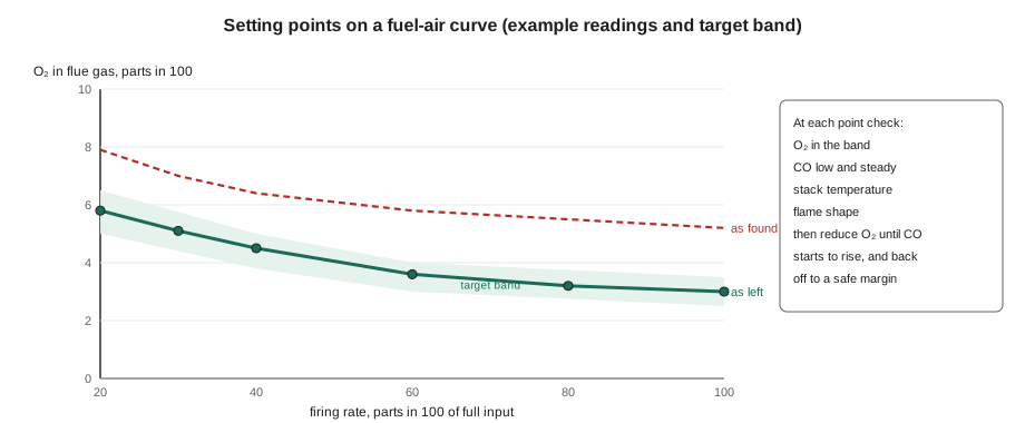
On Friday, October 30, Maureen and Luis returned to the Eastmount Community Centre for the annual tune-up of boiler 1, the 1,465 kW (5,000,000 Btu/h) fire-tube boiler Jonah had seen on his first commercial day. Its modulating burner used a jackshaft with a characterizing cam. The as-found readings told Maureen what the year had done: at high fire the oxygen was 5.2 parts in 100, at low fire 7.9, much more excess air than the 3 and 5.5 or so she had left the year before. "Somebody's been in the linkage, or it's worn," she said. "Either way, it's costing them gas every hour it runs. Today you're tuning it, and I'm watching."
This lesson extends the combustion analysis of GAS-230 to larger, modulating burners. It covers preparing to tune, where and how to sample the flue gas, checking the input, the step-by-step method of setting the fuel-air ratio at each firing rate, finding the carbon monoxide limit and leaving a safe margin, judging the flame by eye, estimating the efficiency gained, and recording the results.
Before you tune
Tuning changes how much air a burner gets at every firing rate, so it is done only after the burner and boiler are known to be sound. The heat exchanger and tubes should be clean, since soot or scale raises the stack temperature regardless of tuning. The fan wheel, air inlet and damper should be clean and free, the linkage tight, the gas train's regulator holding steady, and the combustion air supply to the room adequate, as lesson 3 showed. The safety controls should all be working. The analyzer should be recently calibrated and zeroed in fresh outdoor air before use, its water trap empty and its filter clean. And the building must be able to take the heat: tuning needs the burner to run at each firing rate for several minutes, so in mild weather the technician may need to open more zones, run the boiler with the system bypass open, or fire into a domestic hot water load.
Where to sample
The analyzer's probe goes into a test hole in the flue or breeching downstream of the boiler outlet and upstream of any barometric damper or draft diverter, so that room air admitted by the damper does not dilute the sample. The probe tip should be near the centre of the flue gas stream, where the temperature is highest and the gas well mixed, and the hole must be sealed around the probe so that no air is drawn in. On a boiler with an economizer or a stack heat recovery unit, the readings are taken where the burner maker specifies, usually at the boiler outlet. The combustion air temperature is measured at the burner's air inlet, since the analyzer uses it to calculate efficiency, and the draft or firebox pressure is measured at the points the boiler maker names.
| Measurement | Where | What it tells you |
|---|---|---|
| Oxygen (O₂) | Flue, upstream of the barometric damper | Excess air |
| Carbon monoxide (CO), as measured and air-free | Same sample | Completeness of combustion |
| Stack temperature | Same sample point, probe tip at the hottest part | Heat leaving in the flue gas; fouling |
| Combustion air temperature | Burner air inlet | Needed for the efficiency calculation |
| Draft or firebox pressure | Points named by the boiler maker | Whether the burner and vent are working as designed |
| Gas manifold pressure and meter flow | Train test points and the gas meter | Actual input |
| Nitrogen oxides (NOx), where required | Flue sample | Emissions, for permits and low-NOx burners |
Checking the input
Before adjusting air, the technician confirms the burner is burning the right amount of gas at high fire, since setting air to suit the wrong gas flow is pointless. The most direct check is to clock the gas meter: with every other appliance on that meter turned off, time how long the meter takes to pass a known volume. On a commercial meter delivering elevated pressure, the metered volume is at the line pressure, so it must be corrected to standard pressure, roughly by the ratio of absolute pressures, before multiplying by the heating value. The utility can give the actual heating value of the gas, and, for precise work, the meter's temperature correction. The manifold pressure at the burner should also match the maker's figure for full input.
Worked problem
Clocking the Eastmount meter
With boiler 2, the pool heater and the makeup air unit off, Luis read the meter's index at the start and end of 120 s with boiler 1 at high fire: it had passed 4.00 m³. The meter operates at 14 kPa gauge, atmospheric pressure is 101.3 kPa, and the utility gives a heating value of 37.5 MJ/m³ at standard conditions. Ignoring temperature correction, what is the input, and how does it compare with the 1,465 kW rating?
Show solution
- Flow at meter pressure:
- \[\frac{4.00}{120} \times 3600 = 120 \text{ m}^3/\text{h}\]
- Correction to standard pressure:
- \[\frac{101.3 + 14}{101.3} = 1.138\]
- Flow at standard pressure:
- \[120 \times 1.138 = 136.6 \text{ m}^3/\text{h}\]
- Input:
- \[\frac{136.6 \times 37.5}{3.6} = 1{,}423 \text{ kW}\]
- Fraction of rating:
- \[\frac{1{,}423}{1{,}465} = 0.97\]
Answer: The burner was firing about 97 parts in 100 of its rating, close enough that Maureen left the gas side at high fire alone and tuned the air to suit it. Without the pressure correction, the input would have looked 14 parts in 100 low.
The tuning method
Most burner makers give a tuning procedure for their burners, with target oxygen and carbon monoxide at each firing rate, and it governs. The general method, on a jackshaft or a linkageless burner, goes like this:
- Start at low fire, with the burner warmed up. Confirm the light-off is smooth and the flame stable. Set the gas and air at low fire to the maker's targets, usually with more excess air than at high fire, because mixing is poorer at low velocities.
- Drive the burner to high fire. Confirm the input and the manifold pressure. Set the air for the target oxygen, then check carbon monoxide.
- Find the carbon monoxide limit: slowly reduce the air at that firing rate while watching the analyzer until the carbon monoxide begins to rise sharply, the knee of the curve in lesson 3. Note the oxygen at which it happens. Then add air back to leave a margin above that point, as the maker recommends, commonly about one point of oxygen or more.
- Work through the intermediate points, on a jackshaft by adjusting the cam screws at each position, on a linkageless system by setting each stored point, so the oxygen changes smoothly from low fire to high fire with no rich spots.
- Run the burner up and down through its range several times, watching for carbon monoxide spikes during changes, and repeat a light-off to be sure it is still smooth.
- Record the final readings at every point, and the settings of the regulator, the linkage or the stored curve.
Reading carbon monoxide properly
The analyzer shows carbon monoxide as measured, the concentration in the sample, and usually also air-free, corrected to what it would be with no excess air. Because excess air dilutes the flue gas, an as-measured reading can look low simply because a burner has a lot of excess air; the air-free value removes that effect and lets readings at different oxygen levels be compared. GAS-230 used air-free carbon monoxide for residential limits; commercial burner makers usually give their limits the same way. The correction is:
Worked problem
Air-free carbon monoxide at high fire
With boiler 1 tuned, Luis's high-fire readings were 3.0 parts in 100 oxygen and 22 ppm carbon monoxide as measured. When he reduced the air to find the limit, the carbon monoxide began rising steeply at 1.6 oxygen, where it read 140 ppm as measured. Find the air-free carbon monoxide for both readings, and the margin of oxygen he left above the knee.
Show solution
- At 3.0 oxygen:
- \[22 \times \frac{20.9}{20.9 - 3.0} = 22 \times 1.168 = 25.7 \text{ ppm}\]
- At 1.6 oxygen:
- \[140 \times \frac{20.9}{20.9 - 1.6} = 140 \times 1.083 = 152 \text{ ppm}\]
- Margin above the knee:
- \[3.0 - 1.6 = 1.4 \text{ points of oxygen}\]
Answer: The final setting gives about 26 ppm air-free, well within the maker's limit, with a margin of 1.4 points of oxygen above the point where combustion starts to fail. That margin covers the seasonal drift of lesson 3 and some linkage wear.
Looking at the flame
Instruments come first, but a good technician also looks. Through the sight glass, a well-tuned gas flame on a nozzle-mix power burner is generally compact, stable and anchored to the head, with no wisps of yellow, no lazy, lifting tips and no impingement on the back wall or tubes. A flame that pulses or rumbles, lifts off the head at light-off, or licks the walls needs attention even if the readings look acceptable, because it may be close to instability. Premix burners look different, often a glowing surface with little visible flame. The maker's literature usually shows what the flame should look like, and what it should not.
Estimating the gain
Most analyzers calculate efficiency from the oxygen, the stack temperature and the air temperature. For understanding, a simple approximation of the dry flue gas loss, the heat carried away by the hot dry flue gases, is useful. For natural gas it is about 0.38 times the temperature rise from the combustion air to the stack, in degrees Celsius, divided by the carbon dioxide in parts in 100. It ignores the heat in the water vapour and other smaller losses, so it understates the total loss, but it shows clearly how less excess air and a cooler stack save fuel.
Worked problem
What the tune-up saved
Before tuning, boiler 1 at high fire read 5.2 oxygen and a stack temperature of 210 °C; after, 3.0 oxygen and 200 °C, with combustion air at 20 °C both times. Using a maximum carbon dioxide of 11.7, estimate the dry flue gas loss before and after with loss ≈ 0.38 × (stack − air) ÷ CO₂.
Show solution
- Carbon dioxide before and after:
- \[11.7 \times \frac{20.9 - 5.2}{20.9} = 8.79 \qquad 11.7 \times \frac{20.9 - 3.0}{20.9} = 10.02\]
- Loss before:
- \[0.38 \times \frac{210 - 20}{8.79} = 0.38 \times \frac{190}{8.79} = 8.2\]
- Loss after:
- \[0.38 \times \frac{200 - 20}{10.02} = 0.38 \times \frac{180}{10.02} = 6.8\]
Answer: The dry flue gas loss fell from about 8.2 to about 6.8 parts in 100 of the input, a gain of roughly 1.4 points at high fire. For a boiler burning this much gas through a winter, that is a real saving, and the low-fire improvement adds more.
What Luis found and did
The cause of the drift was a worn bushing where the air damper arm met its connecting rod; the slack let the damper open a little further than the cam intended at every position. Luis replaced the bushing from Bayline's parts kit, retightened the arm, and then tuned the curve point by point, Maureen watching. At high fire he set 3.0 oxygen and found the carbon monoxide knee at 1.6; at low fire he set 5.8, where the carbon monoxide stayed under 40 ppm air-free and the flame held firmly to the head. After a dozen runs through the range he took the final readings, marked the cam screws with paint so any later movement would show, and filled in the tuning sheet with every reading. Maureen initialled it. "You can do boiler 2 next week," she said, "and I'll be in the car."
| Firing rate (parts in 100) | O₂ as found | O₂ as left | CO air-free as left (ppm) |
|---|---|---|---|
| 20 (low fire) | 7.9 | 5.8 | 38 |
| 40 | 6.4 | 4.5 | 31 |
| 60 | 5.8 | 3.6 | 28 |
| 80 | 5.5 | 3.2 | 27 |
| 100 (high fire) | 5.2 | 3.0 | 26 |
Tuning where emissions matter
Some burners, especially low-NOx burners in areas with air quality permits, must meet a limit on nitrogen oxides as well as carbon monoxide. Nitrogen oxides form when nitrogen and oxygen from the air combine in the hottest parts of a flame, so they rise with flame temperature and, up to a point, with excess air. Low-NOx burners cool the flame by staging the air or gas, by running with more excess air, or by recirculating some flue gas into the flame. Tuning them means balancing carbon monoxide, which rises when air is reduced, against nitrogen oxides, which rise as the flame gets hotter, within the window the maker and the permit allow. An analyzer with a nitrogen oxide sensor is then part of the tuning kit, and the readings are recorded for the permit file.
Common mistakes
MistakeTuning a dirty boiler or a burner with a loose linkage.
InsteadClean, repair and tighten first, then tune.
MistakeSampling downstream of the barometric damper.
InsteadSample upstream of any damper or diverter so room air doesn't dilute the reading.
MistakeSetting air at high fire without checking the input.
InsteadClock the meter and check manifold pressure before setting air.
MistakeTuning right at the carbon monoxide knee for the best efficiency.
InsteadLeave the margin the maker recommends above the knee.
MistakeForgetting to record the as-left settings.
InsteadRecord readings and settings at every firing rate for the next technician.
Summary and key terms
- Tuning sets the fuel-air ratio at every firing rate, after the boiler is clean, the linkage tight, the regulator steady, the air supply adequate and the analyzer calibrated.
- Sample upstream of any barometric damper, near the centre of the flue, with the hole sealed.
- Check the input by clocking the meter with pressure correction and checking manifold pressure.
- Set low fire and high fire to the maker's targets, find the carbon monoxide knee by reducing air and leave a margin above it, then set the intermediate points and run through the range.
- Use air-free carbon monoxide, look at the flame, and record everything.
- Lower excess air and stack temperature reduce the dry flue gas loss, which is roughly 0.38 × temperature rise ÷ CO₂ for natural gas.
- Clocking the meter
- Timing a gas meter over a known volume to find the gas flow.
- Pressure correction
- Adjusting a metered volume from line pressure to standard pressure by the ratio of absolute pressures.
- Carbon monoxide knee
- The point at which carbon monoxide begins to rise sharply as air is reduced.
- Air-free carbon monoxide
- Carbon monoxide corrected to what it would be with no excess air.
- Dry flue gas loss
- Heat carried away by the hot dry products of combustion.
- Fuel-air curve
- The set of matched gas and air settings across a burner's firing range.
Practice problems
Work each problem on paper first, then reveal the answer to check.
Where should the analyzer probe go on a boiler with a barometric damper?
Show answer
In the flue upstream of the damper, near the centre of the gas stream.
Why must a metered volume at 14 kPa be corrected?
Show answer
The gas is compressed at line pressure, so it represents more gas at standard pressure.
How do you find the carbon monoxide knee?
Show answer
Slowly reduce the air at a firing rate until carbon monoxide begins to rise sharply.
Find air-free CO for 30 ppm measured at 4.0 oxygen.
Show answer
30 × 20.9 ÷ 16.9 = about 37 ppm.
What caused the drift at Eastmount?
Show answer
A worn bushing in the air damper linkage.
Lesson quiz · 5 questions
Score 60% or more to complete this lesson.
Create a free account to save your progress, take quizzes and earn a certificate.