
GAS-310 · Lesson 11 of 12 · 23 min
Commissioning a commercial burner
▶ Video coming soon A video version of this lesson is on the way.
The old atmospheric boiler at Glenview Public School, the one Jonah and Luis had seen in September, came out over the last week of October, and in its place stood a new packaged fire-tube boiler of the same 530 kW (1,800,000 Btu/h) rating, with a linkageless modulating power burner, a self-checking UV scanner and a gas train with two safety shutoff valves and proof of closure. The mechanical contractor had set and piped it, the electrician had wired it, and the TSSA boiler inspector had accepted the pressure side. On Monday, November 9, Maureen and Luis arrived to commission the burner. "Commissioning is where we prove the boiler is safe, not just that it runs," Maureen said. "Everything gets tested, everything gets written down, and nothing gets fired until the safeties have been proven to shut the fuel off."
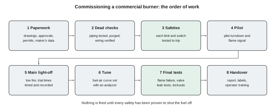
This lesson sets out the order of work for commissioning a commercial power burner: the paperwork, the checks before any gas is admitted, the tests of each safety control, the pilot and main light-off, setting the fuel-air curve, the final tests and the handover. The burner maker's start-up procedure and the codes govern any real job; this lesson gives the pattern that most of them follow.
1. Paperwork
Before touching the boiler, the commissioning technician gathers and reads the documents: the burner maker's installation and start-up manual, the gas train and wiring diagrams, the sequence of operation, the boiler maker's data on firebox pressure and input, the permits and the gas permit or notification TSSA requires, and, for uncertified equipment, the field approval documents of lesson 10. The technician also checks that the installation matches the drawings: that the gas train has the components shown, in the order shown, with the ratings shown; that the vent and breeching are the type the boiler maker lists; and that the combustion air openings or ducts are installed and open. Discrepancies are resolved before anything else happens, not after.
2. Dead checks
With the gas off and the power off, the dead checks begin. The gas piping to the train must have been pressure tested by the installer at the test pressure and duration the code requires, and the test record must be on file. The technician leak tests the train's own joints, which the piping test may not have included, and checks that the regulator vent and switch vents are piped outdoors and terminated properly. On the electrical side, the technician confirms supply voltage and phase, that the burner is grounded, that the control circuit is the voltage the burner expects, and that the wiring of every interlock matches the diagram. The water side must be ready too: the boiler filled and vented, the pumps running, the low-water cutoff and the high limit installed and their wiring checked. The technician then purges the gas line up to the train's manual valve, venting the air outdoors safely as the code describes, so that the first light-off is not delayed by air in the line.
Worked problem
What should the meter show at full input?
Glenview's burner is rated 530 kW. The gas is supplied through a meter at 14 kPa gauge, atmospheric pressure is 101.3 kPa, and the heating value is 37.5 MJ/m³ at standard conditions. How many cubic metres should the meter pass in 60 s at full input?
Show solution
- Gas flow at standard conditions:
- \[\frac{530 \times 3.6}{37.5} = 50.9 \text{ m}^3/\text{h}\]
- Pressure ratio:
- \[\frac{101.3 + 14}{101.3} = 1.138\]
- Flow at meter pressure:
- \[\frac{50.9}{1.138} = 44.7 \text{ m}^3/\text{h}\]
- Volume in 60 s:
- \[\frac{44.7}{60} = 0.745 \text{ m}^3\]
Answer: Luis wrote 0.745 m³ per minute on the start-up sheet as the target, so that when the burner reached high fire he could check the input against it directly.
3. Testing the safeties before firing
Next, with the gas still off at the train's manual valve but the power on, the technician runs the burner management system through its sequence and tests that each safety input stops it. With the manual gas valve closed, the burner will purge, attempt the pilot trial, fail to prove a flame and lock out, which itself is the first test: it shows the pilot trial timing and the lockout. Then, one by one: open each limit, such as the high limit and the low-water cutoff, and confirm the burner stops or will not start; prove that the air switch must be open before the fan starts by checking the sequence, and that it stops the burner when the fan inlet is blocked; confirm the high-fire and low-fire position switches hold the sequence when they are not made; and confirm that the proof of closure switches hold the start if a valve is not proven closed. The low and high gas pressure switches can be checked for wiring at this stage by opening them, and are tested for setting with real gas pressure later.
4. The pilot
With the safeties proven, the technician admits gas to the pilot train only, with the main manual valve still closed, and lights the pilot through a normal sequence. The pilot flame signal is recorded, and the spark test of lesson 6 confirms the detector does not see the igniter spark. Then comes the pilot turndown test, one of the most important tests on any burner with a pilot: the pilot gas is reduced, by the pilot regulator or a needle valve as the maker directs, until the flame signal falls to just above the control's minimum holding level. That is the smallest pilot the flame safeguard will accept. The main gas is then admitted, and the burner must light its main flame smoothly and promptly from that minimum pilot. If it does not, a weak pilot that the detector still accepts could fail to light the main flame cleanly, letting gas collect before a delayed, violent ignition. The fix is to re-aim the scanner so that it proves only a pilot large enough to light the main flame reliably, then repeat the test. The pilot is then set back to its normal size.
Worked problem
The Glenview pilot turndown
The control's minimum holding signal is 1.25 V on a 0 to 5 V scale. At normal pilot gas pressure, the pilot signal was 2.6 V. Luis turned the pilot gas down until the signal read 1.4 V. With that pilot, the main flame lit at low fire 1.5 s after the main valves opened, smoothly, with no rumble. Express the turned-down signal as a fraction of the normal one, and decide whether the test passes.
Show solution
- Turned-down signal as a fraction of normal:
- \[\frac{1.4}{2.6} = 0.54\]
- Margin above the minimum holding signal:
- \[1.4 - 1.25 = 0.15 \text{ V}\]
- The main flame lit smoothly and promptly from the minimum pilot.
Answer: The test passes: even a pilot only about half its normal strength, barely enough for the detector to accept, lit the main flame smoothly. Luis restored the pilot to its normal setting and recorded both readings.
5. Main light-off
With the main manual valve opened, the technician lets the burner run a full sequence to the main trial for ignition at low fire, watching the flame through the sight glass and the readings on the analyzer. The first main flame is held at low fire. The technician times the prepurge, the pilot trial and the main trial and compares them with the label and the maker's figures, as lesson 7 did, and checks that the interrupted pilot goes out at the end of the main trial and the main flame signal holds on its own. The analyzer's first job is safety: if carbon monoxide is high at the first light-off, the burner is shut down and the air and gas are checked before going further.
6. Setting the curve
With a stable low-fire flame, the technician sets the fuel-air curve as lesson 9 described, starting from the maker's preset values: low fire first, then high fire with the input confirmed by clocking the meter and checking manifold pressure, then each intermediate point. On a linkageless system, each point is stored in the controller. The technician also tests the low and high gas pressure switches with real pressure: raising the regulator setting, or using a test connection, until the high switch trips; reducing the supply with the inlet valve until the low switch trips; and recording the trip pressures. The firing-rate controller is set up, with its set points, low-fire hold and reset curve if used.
7. Final tests
With the burner tuned, the final tests prove its behaviour under fault conditions at operating temperature. The flame failure test: with the main flame running, close the main and pilot manual valves, or follow the maker's method, and time the shutdown, which must be within the control's flame failure response time and end in lockout. The valve leak tests of lesson 5 on both safety shutoff valves, and on the pilot valves, recorded. A repeat test of the low-water cutoff by the method the boiler maker gives, usually by draining the cutoff's float chamber or lowering the water, with the burner firing, to show that it stops the burner. A power failure test: cut the power during the run and confirm the valves close and the burner restarts safely, with a full purge, when power returns. And a final run through the sequence from cold, with every reading recorded.
| Test | Method | Pass when |
|---|---|---|
| Pilot trial and lockout | Main and pilot gas off at manual valves; run sequence | Locks out at the end of the pilot trial |
| Spark test | Pilot gas off, spark on | Flame signal stays below minimum |
| Pilot turndown | Pilot reduced to minimum accepted signal | Main flame lights smoothly from it |
| Air proving | Block fan inlet during run | Burner shuts down |
| Low and high gas pressure switches | Change actual pressure | Each trips near its setting |
| Flame failure | Close fuel during run | Shutdown within the response time, then lockout |
| Valve seat leakage | Bubble test or valve proving | Within the maker's allowance |
| Low-water cutoff | Lower water by the boiler maker's method | Burner stops; manual reset where required |
| Power failure | Remove power during run | Valves close; safe restart with purge |
8. Handover
The job is not done until the owner can run the equipment and the next technician can understand it. The commissioning technician completes the start-up report with every reading and setting: flame signals, trial times, switch settings and trip points, valve test results, combustion readings at each firing rate, gas pressures and input. Settings are labelled on the equipment where the maker allows. The owner's operator or caretaker is shown how the boiler starts, what the displays mean, what a lockout looks like, why it must not simply be reset, how to shut the boiler down in an emergency, and whom to call. Copies of the report and the manuals go to the owner, and Bayline keeps its own. Where an inspection is still to come, the report is ready for the inspector.
At Glenview, the work took the whole day. Everything passed, with one exception: the high gas pressure switch tripped well above the setting on its dial when tested with real pressure, so Luis reset it until it tripped at the maker's figure on the gauge and recorded both. Maureen showed the school's caretaker, Doug Pereira, the new display, the lockout history screen and the emergency shutoff switch at the door, and left him a laminated card: "If it locks out, call us; reset once only if we tell you to." She signed the start-up report, and Luis, who had done most of the testing under her eye, signed it as the technician who performed the tests. A G.1 had supervised and signed; Luis's hours went into his log. Any TSSA inspector who called would find every test result in the binder on the boiler room wall.
What commissioning commonly finds
Maureen keeps a running list of what Bayline's commissioning visits have found over the years, and she showed it to Luis at the end of the Glenview day. Few new installations pass every check on the first try, which is exactly why commissioning exists.
| Finding | Why it matters |
|---|---|
| Fan motor wired to run backwards | A backwards fan moves far less air; the air switch may still make |
| Regulator vent not piped outdoors, or not terminated | A diaphragm failure would release gas into the room |
| Pressure switches far from their dial settings | Little or no protection, or nuisance trips |
| Strainer full of construction debris | Can hold valve seats open and limit flow |
| Combustion air opening blocked or undersized | The burner runs short of air when the room is closed up |
| Scanner sighted on the pilot only | Main flame may be poorly supervised at some firing rates |
| Low-water cutoff not wired into the limit string | The burner could fire a dry boiler |
Common mistakes
MistakeFiring a new burner before testing its safeties.
InsteadProve every safety stops the burner before the first light-off.
MistakeSkipping the pilot turndown test.
InsteadProve the main flame lights smoothly from the smallest pilot the detector accepts.
MistakeTrusting pressure switch dials.
InsteadTest switch trip points with real pressure and record them.
MistakeLeaving without operator training.
InsteadShow the operator the displays, lockouts, emergency shutdown and whom to call.
MistakeWriting a report with readings but not settings.
InsteadRecord settings as well as readings so the next technician can compare.
Summary and key terms
- Commissioning follows an order: read and check the paperwork and the installation against the drawings; do dead checks of piping tests, train leak tests, vents, electrical supply, interlock wiring and the water side, and purge the gas line; test every safety input with the gas off; light the pilot, run the spark test and the pilot turndown test; light the main flame at low fire and time the sequence; set the fuel-air curve, confirm input, and test the gas pressure switches with real pressure; then run final tests of flame failure, valve seat leakage, low-water cutoff and power failure.
- The handover includes a complete start-up report of readings and settings, labels, and operator training.
- Commissioning
- The process of testing and setting up new equipment to prove it works safely as designed.
- Dead checks
- Checks done with gas and power off before the first start.
- Pilot turndown test
- A test that the main flame lights smoothly from the smallest pilot the flame safeguard will accept.
- Spark test
- A test that the flame detector does not see the ignition spark as flame.
- Flame failure test
- A test that the burner shuts down within the response time when the flame is lost.
- Start-up report
- The record of all readings, settings and test results from commissioning.
Practice problems
Work each problem on paper first, then reveal the answer to check.
Why are safeties tested before the first light-off?
Show answer
So no fuel is ever fired before each safety has been shown to stop it.
What does the pilot turndown test prove?
Show answer
That the smallest pilot the detector accepts still lights the main flame smoothly.
How are gas pressure switches tested at commissioning?
Show answer
By changing the real pressure until each trips, and recording the trip points.
Name three final tests.
Show answer
Flame failure, valve seat leakage, low-water cutoff; also power failure.
What did Luis find wrong at Glenview?
Show answer
The high gas pressure switch tripped above its dial setting, so he reset it to the gauge.
Lesson quiz · 5 questions
Score 60% or more to complete this lesson.
Create a free account to save your progress, take quizzes and earn a certificate.