
GAS-310 · Lesson 6 of 12 · 24 min
Flame safeguards and burner management systems
▶ Video coming soon A video version of this lesson is on the way.
Brightwater Dairy in Winona, on Hamilton's east edge runs its process steam boiler around the clock from August to May, often for weeks without the burner shutting off. The boiler, 2,930 kW (10,000,000 Btu/h) with a modulating power burner, still had its original 1998 flame safeguard, with an ultraviolet scanner of the kind that checks itself only when the burner starts. The insurer's inspector had written it up in the spring: a burner that runs continuously needs a flame detector that checks itself continuously. On Monday, October 26, during the plant's planned weekend-to-Monday shutdown, Maureen and Luis replaced the old control with a new burner management system and a self-checking scanner. "Today we're replacing the brain and the eyes," Maureen told Luis as they unpacked it, "so we're going to understand both before we wire anything."
This lesson explains how a flame safeguard watches a flame, the three common kinds of flame detector, why ultraviolet scanners on continuous duty must check themselves, how flame signals are measured and judged, and what a burner management system does with its inputs and outputs. Lesson 7 follows the burner management system through a start sequence.
What a flame safeguard does
A flame safeguard, also called a combustion safeguard or primary control, is the device that allows gas to flow only when a flame is proven, and stops it when the flame is lost. It has three basic duties. Before each start it makes a safe-start check: it must see no flame before ignition, because a flame signal when there should be none means either a real fire in the chamber from leaking gas or a failed detector, and either way the burner must not start. During the trial for ignition, it must prove the flame within a strict time, or close the valves and lock out. And while the burner runs, it must supervise the flame continuously and close the safety shutoff valves within its flame failure response time if the flame is lost. On residential appliances GAS-220 called this the ignition control; on commercial equipment it is a larger, separate control with a flame amplifier, a programmer that times the sequence, and a display.
Seeing the flame
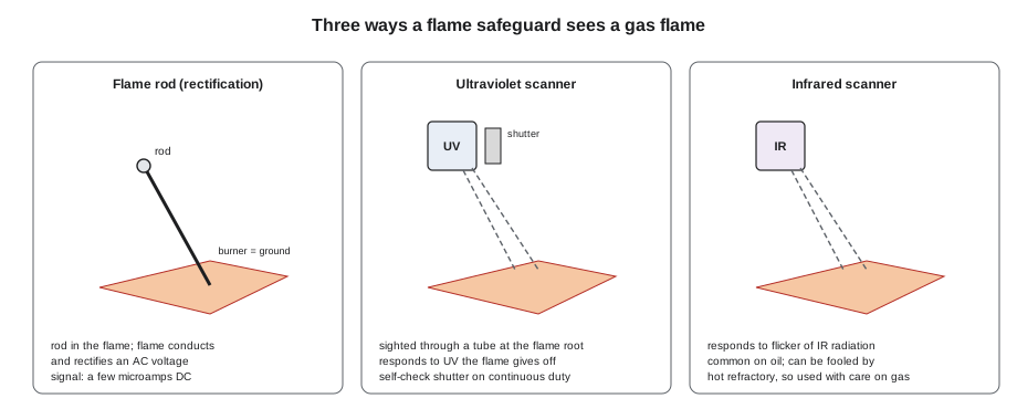
There are three common ways to detect a gas flame.
A flame rod, as on the residential appliances of GAS-220, is a heat-resisting metal rod placed in the flame. The control applies an AC voltage between the rod and the burner, which is grounded. A flame conducts electricity and, because the burner's grounded area is much larger than the rod, it conducts better in one direction than the other, so the current through it is partly rectified into DC. The control looks for that small DC current, typically a few microamps, which only a real flame can produce; a short circuit from the rod to ground produces AC, not DC, and is not mistaken for flame. Flame rods are common on pilots and on smaller burners, but they sit in the flame and wear out, and they need a good ground path.
An ultraviolet scanner contains a sealed tube filled with gas that conducts in pulses when ultraviolet radiation strikes it. A gas flame gives off strong ultraviolet radiation from its root, near the burner head. The scanner is mounted on a sight tube aimed at the flame root, often with a cooling air connection and a lens or window that must be kept clean. UV scanners respond quickly and do not need to be in the flame. Their weakness is that the tube can fail by running away, beginning to conduct on its own with no ultraviolet present, which looks exactly like a flame. On a burner that starts often, the safe-start check catches a runaway tube at the next start. On a burner that runs for days or weeks, a tube that ran away during the run would keep the valves open after a flame failure. So burners on continuous duty, generally those that may run for more than about 24 hours without cycling off, need a self-checking UV scanner with a mechanical shutter that closes many times a minute. Each time it closes the signal must drop; if it does not, the tube has failed and the control shuts down.
An infrared scanner responds to the flickering infrared radiation from a flame. It is used mainly on oil flames, which radiate strongly in infrared. On gas, it must be applied carefully, because hot refractory brick also gives off infrared and can flicker in hot gases, so an infrared scanner could see glowing refractory as flame after a flame failure. Some modern scanners combine UV and infrared sensing, or use solid-state sensors, with self-checking built in.
| Detector | Senses | Strengths | Watch for |
|---|---|---|---|
| Flame rod | Rectified current through the flame | Simple, cannot be fooled by a short circuit | Wears in the flame; needs a good ground |
| UV scanner, non-self-checking | Ultraviolet from the flame root | Fast, outside the flame | Tube runaway; acceptable only on burners that cycle |
| UV scanner, self-checking | Ultraviolet, with a shutter test | Detects its own failure continuously | Shutter wear; dirty lens |
| Infrared scanner | Flickering infrared | Good on oil flames | Hot refractory can mimic flame |
Flame signal
Every flame safeguard shows a flame signal, a number that tells how strongly the detector sees the flame. The scale depends on the control: some show microamps, some volts DC at a test jack, some a number from 0 to 20 or 0 to 100 on a display. The maker gives a minimum signal below which the control will not hold the flame, and a recommended range for reliable operation. A signal that is barely above the minimum will cause nuisance shutdowns as the flame shifts or the lens dirties. A signal that is high when there should be no flame shows a detector problem. On commissioning and at each service, the technician records the signal for the pilot alone, the main flame at low fire, and the main flame at high fire, and checks that the scanner does not see the ignition spark as flame: with the pilot gas off and the spark on, the signal must stay below the minimum. A UV scanner aimed so that it sees the spark could prove a flame that isn't there.
Worked problem
Is the new scanner sighted well?
Brightwater's new control shows flame signal on a 0 to 5 V DC scale. The maker gives a minimum of 1.25 V for holding the flame and recommends at least 2.0 V for reliable operation. After installing the scanner, Luis recorded: spark only (pilot gas off) 0.1 V; pilot alone 2.4 V; main flame at low fire 3.5 V; main flame at high fire 4.1 V. Are these acceptable, and what margin does the weakest flame reading have over the minimum?
Show solution
- Spark only: 0.1 V, well below 1.25 V, so the scanner does not see the spark as flame.
- Weakest flame reading is the pilot, 2.4 V, above the recommended 2.0 V.
- Margin over the minimum:
- \[2.4 - 1.25 = 1.15 \text{ V}\]
- As a multiple of the minimum:
- \[\frac{2.4}{1.25} = 1.9\]
Answer: All four readings are acceptable. The pilot signal is nearly twice the minimum, and the main flame signals are strong at both firing rates. Luis wrote all four on the start-up sheet so the next technician can compare.
Flame failure response time
When the flame is lost, the control must remove power from the safety shutoff valves within its flame failure response time, set by its listing and the type of equipment, typically within about four seconds or less on commercial burners. The valves then close in about a second. During that time, gas keeps flowing into a combustion chamber with no flame. The response time is a property of the control and its amplifier, printed on its label, and a replacement control must have a response time no longer than the original and suited to the equipment. That is one reason controls are replaced only with the models the burner maker or the code permits.
Worked problem
Gas admitted after a flame failure
Brightwater's burner fires 2,930 kW. The new control's flame failure response time is 4 s, and the safety shutoff valves close in 1 s. Using a heating value of 37.5 MJ/m³, about how much gas could enter the combustion chamber at full input between the flame going out and the valves closing?
Show solution
- Gas flow at full input:
- \[\frac{2{,}930 \times 3.6}{37.5} = 281 \text{ m}^3/\text{h} \;\to\; \frac{281}{3600} = 0.0781 \text{ m}^3/\text{s}\]
- Gas in 5 s:
- \[0.0781 \times 5 = 0.39 \text{ m}^3\]
Answer: Up to about 0.4 m³ of gas could enter, enough to make a burnable mixture in a few cubic metres of chamber if it stayed there. In practice the fan keeps running and sweeps it out, and the control then runs a post-purge, but the example shows why response time matters and why a control must never be replaced with a slower one.
Lockout, recycle and reset
When a flame safeguard detects a dangerous condition, such as a failed safe-start check, no flame at the end of a trial for ignition, or a flame failure during the run, it goes to safety shutdown: it closes the valves, runs the fan for a post-purge, and, on most commercial controls, locks out. A locked-out control will not restart until someone presses its reset button, and on many controls the reset must be done at the control itself, not remotely. Some controls are allowed to recycle once after a flame failure during the run, purging and attempting one new light-off, where the code and the listing permit; a second failure locks out. Modern controls keep a lockout history with the fault, the sequence step and often the flame signal and the time, and that history is the first thing a technician should read. Pressing reset without reading it erases the clues, and pressing it repeatedly is how explosions happen: each failed trial puts more unburned gas into the chamber.
Burner management systems
On larger commercial and most industrial equipment, the flame safeguard is part of a burner management system, or BMS, which combines the flame amplifier, a programmer that runs the light-off sequence, interfaces to the firing-rate control, and monitoring of every safety input. A BMS may be a dedicated burner control or, on large industrial systems, a safety-rated programmable controller. Whatever its form, it does the same thing: it proves that every condition needed for safe operation is satisfied before it will allow fuel, it runs the sequence with fixed, tamper-resistant timings, and it shuts the fuel off when any condition is lost.
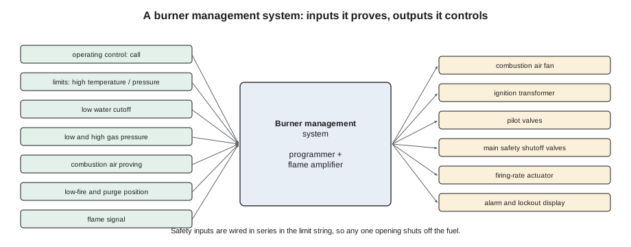
The inputs fall into groups. The operating control, such as a boiler water thermostat or a steam pressure control, starts and stops the burner normally. The limits, such as the manual-reset high temperature or high pressure limit and the low water cutoff, shut the burner off when a dangerous water-side condition arises; they are wired in series in the limit string, so that any one of them opening removes power from the burner's safety circuit. The fuel interlocks are the low and high gas pressure switches and the proof of closure switches. The air interlocks are the combustion air proving switch, which proves the fan is moving air, and position switches that prove the air damper is at high fire for the purge and back at low fire for light-off. And the flame signal comes from the detector. Some interlocks must be proven before the start (pre-ignition interlocks), and some must stay made throughout the run (running interlocks).
The Brightwater replacement
The work took most of the day. With the boiler locked out, the gas train isolated and the plant's own lockout tags on the main disconnect, Maureen photographed and labelled every wire on the old control before removing it. The new BMS mounted on the same wiring subbase in the panel, but its terminal numbers differed, so she worked from the burner maker's conversion drawing rather than copying the old wiring. Luis ran a new shielded cable for the self-checking scanner in its own conduit, away from the ignition and motor wiring, as the instructions required, and installed a new sight tube with a cooling air connection from the burner fan. The old scanner's sight tube had been aimed so that it saw mostly the pilot and little of the main flame root, which explained occasional low-fire flame failures in the boiler log.
Before firing, they checked every input: each limit opened the circuit, each gas pressure switch tripped when its pressure was changed, the air switch dropped out when Luis blocked the fan inlet with a board, and the low-fire and high-fire position switches made at the right damper positions. They confirmed the control's flame failure response time on its label matched the burner maker's requirement. Then they ran the spark test, the pilot turndown test of lesson 11, and recorded the flame signals in the example above. Finally, with the main flame at low fire, Maureen closed the pilot and main manual valves to simulate a flame failure, and Luis timed the shutdown: the valves closed and the lockout light came on in about three seconds, within the label value. "Now the inspector can sleep," Maureen said, "and so can the night shift."
Common mistakes
MistakeReplacing a flame safeguard with any control that fits the subbase.
InsteadUse only the replacement the burner maker or code permits, with a suitable response time and features.
MistakeUsing a non-self-checking UV scanner on a burner that runs continuously.
InsteadContinuous-duty burners need a self-checking scanner, or another detector type the code allows.
MistakeAccepting a flame signal barely above the minimum.
InsteadAim the scanner and clean the lens until the signal has a good margin.
MistakePressing reset repeatedly after a lockout.
InsteadRead the lockout history, find the cause, and purge before any further attempt.
MistakeRunning scanner wiring in the same conduit as ignition leads.
InsteadKeep scanner wiring separate, as the maker instructs, to avoid false signals.
Summary and key terms
- A flame safeguard makes a safe-start check, proves the flame within a set trial time, supervises it while running, and closes the safety shutoff valves within its flame failure response time if it is lost.
- Flame rods detect rectified current through the flame; ultraviolet scanners detect the flame root's UV and can fail by running away, so continuous-duty burners need self-checking scanners with a shutter; infrared scanners suit oil but can mistake hot refractory for flame.
- Flame signals are recorded for pilot, low fire and high fire, and the scanner must not see the spark.
- Controls lock out on dangerous conditions and keep a history that must be read before reset.
- A burner management system proves limits, fuel and air interlocks and flame before powering the fan, igniter and valves, and shuts the fuel off when any is lost.
- Flame safeguard
- A control that allows fuel only when a flame is proven and stops it when the flame is lost.
- Safe-start check
- A check that no flame signal is present before ignition.
- Flame failure response time
- The time a flame safeguard takes to de-energize the fuel valves after the flame is lost.
- Self-checking scanner
- A flame scanner that tests itself continuously, for example with a shutter.
- Lockout
- A safety shutdown that requires a manual reset before the burner can restart.
- Limit string
- The series circuit of limits and interlocks that must all be closed for the burner to run.
- Burner management system
- A control system that proves safety conditions, runs the light-off sequence and supervises the flame.
- Running interlock
- A safety condition that must remain satisfied throughout the burner's run.
Practice problems
Work each problem on paper first, then reveal the answer to check.
Why must a continuous-duty burner have a self-checking UV scanner?
Show answer
A UV tube can run away and mimic a flame; on a burner that rarely cycles, only continuous self-checking would catch it.
What should the flame signal be with the spark on and the pilot gas off?
Show answer
Below the control's minimum, showing the scanner does not see the spark.
What does a safe-start check look for?
Show answer
No flame signal before ignition.
Why is pressing reset repeatedly dangerous?
Show answer
Each failed trial admits more unburned gas into the chamber, and the history is lost.
Name the input groups of a burner management system.
Show answer
Operating control, limits, fuel interlocks, air interlocks and flame signal.
Lesson quiz · 5 questions
Score 60% or more to complete this lesson.
Create a free account to save your progress, take quizzes and earn a certificate.