
GAS-220 · Lesson 5 of 12 · 24 min
Hot surface and direct spark ignition
▶ Video coming soon A video version of this lesson is on the way.
The furnace in the narrow brick row house in Corktown was only eleven years old, but its owner was afraid of it. Every time it started, she said, it made a "whump" that she could feel through the kitchen floor. Rosa and Jonah went on Monday, October 26. Rosa set the thermostat to call and had Jonah watch through the burner door's sight opening with his hands well clear. The inducer ran, the igniter glowed orange, the gas valve clicked open, and for what felt like a long second nothing happened. Then the burners lit all at once with a soft boom that rattled the door. "That's a delayed ignition," Rosa said. "The gas is reaching the igniter late, or the igniter isn't where the gas is. Either way, it's getting worse every time it does that, and one day it'll crack the heat exchanger or blow the door off."
Most furnaces built in the last thirty years, and many boilers and water heaters, light their main burner directly, with no pilot at all. They use hot surface ignition, a ceramic element that glows hot enough to light gas on contact, or direct spark ignition, a spark at the main burner. This lesson explains how both work, how they are timed by the control board, how to handle, test and position an igniter, and how to find the cause when a direct-ignition appliance will not light or lights badly. GAS-130 covered the igniter's electrical circuit and the cracked igniter on Locke Street; this lesson covers the ignition system as a whole.
Hot surface igniters
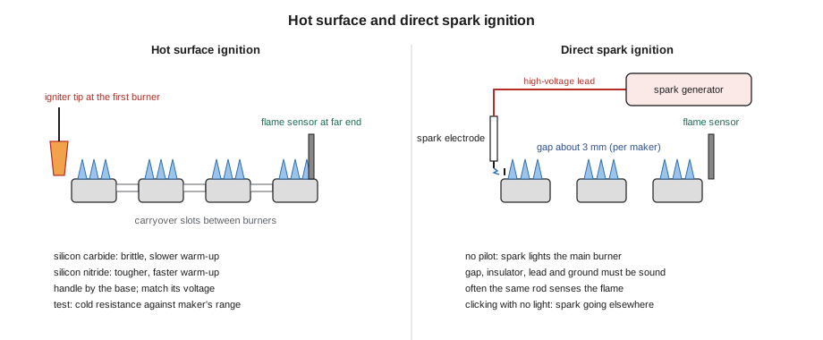
A hot surface igniter, or HSI, is a small ceramic element that heats up when current passes through it, much like the filament of an old light bulb but far tougher. When it is hot, its surface is well over 1,000 °C, about 2,000 °F, hotter than the temperature at which natural gas or propane ignites, so gas that touches it lights at once. The igniter is mounted so that its tip sits in the path of the gas leaving the first burner, a short distance from the burner face, in the position the maker's diagram shows. From the first burner the flame spreads along the row through the carryover or crossover slots between the burners.
Two materials are common. Silicon carbide igniters, often a flat, zigzag element, were the first type and are still in many furnaces. They are brittle and break easily if touched, dropped or bumped by a vacuum nozzle, and they take some time to reach full temperature, commonly 15 seconds or more and up to about 45 on some designs. Silicon nitride igniters, usually a small flat or round paddle with the element sealed inside, are much tougher and heat up faster, often in a few seconds to about 20, which is why most current furnaces use them. Igniters are built for a particular voltage: most run on 120 volts, some on a reduced voltage from the board, often about 80 volts, and some on 24 volts. An igniter is replaced only with the part the maker specifies, or a listed replacement made for that voltage and position.
The hot surface ignition sequence
On a typical induced-draft furnace with hot surface ignition, the board runs a sequence like this. After the call for heat, it checks the safety chain and the open pressure switch, starts the inducer and waits for the pressure switch to close. The pre-purge runs, commonly about 15 to 30 seconds. The board then powers the igniter for its warm-up time, set in the board to suit that igniter. When the warm-up ends, the board opens the gas valve and begins the trial for ignition, commonly about 4 to 7 seconds; on most designs the igniter stays powered during part or all of the trial. Within the trial, the flame sensor, a separate rod in the flame at the far end of the burner row on most furnaces, must prove flame by rectification. If it does, the igniter turns off and the burner runs; if it does not, the board closes the valve, runs an inter-purge and tries again, usually up to three or four times before it locks out.
The far-end position of the flame sensor matters. A flame proved at the last burner shows that the flame has carried across every burner in the row. A sensor at the first burner would prove only that one burner had lit, and the others could be pouring out unburned gas. This is one reason a burner assembly is always put back exactly as it came out, with every burner in its slot and every carryover clean.
Worked problem
How long before warm air
A furnace's board has a 20-second pre-purge, a 17-second igniter warm-up and a 4-second trial for ignition, and it starts the blower 30 seconds after flame is proved. If ignition succeeds on the first try at the end of the trial, how long after the thermostat calls does the blower start? If the first trial fails and the board runs a 20-second inter-purge, a second warm-up and a successful second trial, how long is it?
Show solution
- First try:
- \[20 + 17 + 4 + 30 = 71 \text{ s}\]
- Second try adds the failed trial's time after the first warm-up, an inter-purge, and a second warm-up and trial:
- \[20 + 17 + 4 + 20 + 17 + 4 + 30 = 112 \text{ s}\]
Answer: The customer waits a little over a minute for warm air when the furnace lights first time, and nearly two minutes when it needs a second try. A furnace that regularly needs two or three tries is showing an ignition fault even if the customer has never seen it lock out, which is why the board's fault history is worth reading on every service call.
Handling, positioning and testing an igniter
Igniters are handled by their ceramic base or mounting bracket, never by the element. Skin oils left on a silicon carbide element create hot spots that crack it within a few heats, and a knock against the burner or the cabinet can break it outright. When a burner assembly is removed for cleaning, the igniter is removed first or protected, and the vacuum nozzle is kept well away from it.
Position is critical. The maker's diagram gives where the igniter tip sits relative to the burner, often within a few millimetres of a fixed point, and a bracket that has been bent or a universal igniter mounted in a different position can put the tip outside the stream of gas. Then the gas has to travel or mix before it reaches the hot surface, and it lights late. A universal replacement igniter is supplied with adapters and instructions precisely so that its tip can be put where the original was.
To test an igniter, the power is turned off and its plug disconnected, and its cold resistance is measured between the two pins. An open element, a reading of OL, means it is cracked and must be replaced. A resistance far outside the maker's range means it is failing. Cold resistances vary widely with the material and the model: many silicon carbide igniters read roughly 40 to 90 ohms, while silicon nitride igniters vary more from model to model, so the figure that counts is the one in the furnace's or the igniter's literature. During warm-up the technician also checks the voltage at the igniter plug, with the meter leads held by their insulated grips and hands clear of the element. That voltage should be close to the igniter's rating.
Worked problem
Why low voltage makes a weak igniter
An igniter's heating power is proportional to the square of the voltage across it, if its resistance stays about the same. A 120-volt igniter is measured at 108 volts during warm-up, because the furnace is on a long, undersized circuit that drops voltage under load. About what fraction of its rated power is it producing?
Show solution
- Ratio of the voltages:
- \[\frac{108}{120} = 0.90\]
- Power ratio:
- \[0.90^2 = 0.81\]
Answer: The igniter is producing only about 81 parts in 100 of its rated power. It will glow, but it may not reach full temperature within the board's fixed warm-up, so ignition becomes slow or unreliable. A voltage problem at the igniter is an electrical supply problem; GAS-130 showed how to trace a voltage drop, and on Bayline's jobs, circuit work goes to its electrical partner.
| Symptom | What to check | Usual cause |
|---|---|---|
| Igniter never glows; no voltage at plug during warm-up | Pressure switch proved? Board output? | Earlier step not met, or board relay fault |
| Igniter never glows; full voltage at plug | Cold resistance | Cracked igniter (OL) |
| Igniter glows dimly or slowly | Voltage at plug; resistance against maker's range | Low supply voltage or ageing igniter |
| Igniter glows; no gas | Voltage at valve during trial; inlet pressure | Board not opening valve, valve fault or no gas |
| Burner lights late with a bang | Igniter position; carryovers; pressures | Misplaced igniter, dirty carryovers, low manifold pressure |
| Burner lights, then shuts off in a few seconds | Flame signal in microamps | Flame sensing fault (lesson 6) |
Direct spark ignition
Direct spark ignition, or DSI, lights the main burner with a spark, the same way an IPI system lights its pilot, but with no pilot in between. A spark generator, built into the control board or a separate module, produces a high-voltage spark across a gap at the main burner, and the board opens the gas valve at the same time. As with hot surface ignition, a flame sensor proves the flame within a short trial for ignition, often only a few seconds, and on many designs the same rod that made the spark then senses the flame. DSI is common on power-vented and condensing water heaters, tankless water heaters, many boilers, cooktop burners and some furnaces and rooftop units.
A DSI electrode needs the same care as an IPI electrode: the gap set to the instructions, often about 3 mm, a sound ceramic insulator, a clean electrode tip, a high-voltage lead in good condition and routed clear of metal, and a good burner ground. Because the spark lights a full main burner rather than a small pilot, a weak or misplaced spark causes delayed ignition in the same way a misplaced hot surface igniter does. A clicking spark that never lights the burner, with gas confirmed at the valve, usually means the spark is jumping somewhere other than the gap: across a cracked insulator, to a bracket, or along a wet surface.
| System | What lights the main burner | How flame is proved | Gas between calls |
|---|---|---|---|
| Standing pilot | A pilot that burns continuously | Thermocouple or thermopile | Pilot gas all the time |
| Intermittent pilot | A pilot lit by spark on each call | Flame rectification at the pilot | None |
| Hot surface | A glowing ceramic igniter | Flame rectification at the main burner | None |
| Direct spark | A spark at the main burner | Flame rectification, often the same rod | None |
Delayed ignition and how to prevent it
Delayed ignition, the problem in Corktown, has a small number of causes, and all of them come down to gas reaching the ignition source late or not mixing properly when it gets there. The igniter or electrode may be out of position. The carryover slots between burners may be blocked with rust or debris, so that the flame crosses slowly from burner to burner. The manifold pressure may be low, so the gas leaves the burners slowly. The burners may be dirty or misaligned on their orifices. The igniter may be weak, or the spark misdirected. And on an induced-draft furnace, a partly blocked heat exchanger or vent can change the flow through the burner box enough to disturb the flame front.
Rosa and Jonah found two of these in the row house. The furnace had a universal silicon nitride igniter that another company had fitted two winters before, mounted with its tip about 5 mm farther from the burner face than the maker's diagram showed, and two of the carryover slots were partly blocked with rust scale. Rosa pulled and cleaned the burners, cleaned the carryovers, fitted the igniter the maker specified in its original position, and checked the manifold pressure, which was correct. Then she had Jonah watch ten starts. Every one lit within a second of the valve opening, quietly, across all four burners. Before leaving, Rosa inspected the heat exchanger and the burner door gasket for damage from the earlier bangs and recorded what she found on the service report.
Common mistakes
MistakeHandling a silicon carbide igniter by its element.
InsteadHandle it by the base; oils and knocks crack the element.
MistakeFitting a universal igniter in whatever position the bracket allows.
InsteadUse the adapters to put the tip exactly where the maker's diagram shows.
MistakeCondemning an igniter without measuring it.
InsteadMeasure its cold resistance against the maker's range and the voltage at the plug during warm-up.
MistakeFitting a 120-volt igniter where the board supplies 80 volts, or the reverse.
InsteadMatch the replacement to the appliance's igniter voltage.
MistakeIgnoring a soft bang on light-off because the furnace still runs.
InsteadTreat any delayed ignition as a fault and find its cause.
Summary and key terms
- Hot surface ignition uses a ceramic element, silicon carbide or silicon nitride, that glows well over 1,000 °C and lights the main burner directly.
- The board runs a pre-purge, an igniter warm-up and a trial for ignition of a few seconds, and a flame sensor, usually at the far end of the burner row, must prove the flame.
- Igniters are handled by the base, matched to their voltage and set exactly where the maker shows.
- Test them by cold resistance, against the maker's range, and by voltage at the plug during warm-up; low voltage greatly reduces their power.
- Direct spark ignition lights the main burner with a spark and needs a correct gap, a sound insulator and a good ground.
- Delayed ignition comes from a misplaced igniter or electrode, dirty carryovers, low manifold pressure or a weak ignition source, and is always treated as a fault.
- Hot surface igniter (HSI)
- A ceramic element heated by current until it is hot enough to light gas on contact.
- Silicon carbide
- An early, brittle igniter material with a longer warm-up.
- Silicon nitride
- A tougher igniter material that heats faster.
- Warm-up
- The time the board powers the igniter before it opens the gas valve.
- Carryover
- The slots or channels that carry flame from one burner to the next.
- Direct spark ignition (DSI)
- Ignition of the main burner by a spark, with no pilot.
- Cold resistance
- An igniter's resistance measured at room temperature with the power off.
Practice problems
Work each problem on paper first, then reveal the answer to check.
Why is the flame sensor usually at the far end of the burner row?
Show answer
So that proving the flame shows it has carried across every burner.
What does an igniter that reads OL mean?
Show answer
Its element is open, usually cracked, and it must be replaced.
Why does an igniter on a low-voltage supply light poorly?
Show answer
Its power falls with the square of the voltage, so it may not reach full temperature.
Name two causes of delayed ignition.
Show answer
A misplaced igniter and blocked carryovers; also low manifold pressure or a weak spark.
What does a clicking DSI spark that never lights the burner suggest, with gas at the valve?
Show answer
The spark is jumping somewhere other than the gap.
Lesson quiz · 5 questions
Score 60% or more to complete this lesson.
Create a free account to save your progress, take quizzes and earn a certificate.