
GAS-220 · Lesson 11 of 12 · 24 min
Sequence of operation and troubleshooting
▶ Video coming soon A video version of this lesson is on the way.
On Sunday, November 8, Rosa let Jonah lead a call for the first time, with her standing behind him and saying nothing unless he asked. The furnace was a 2005 two-stage model in a 1960s backsplit in Rosedale, and the owner said it kept "almost working": it would light, run for a minute or so, shut off, and try again, until the light on the board started flashing and it gave up. Jonah's hands wanted to go straight to the flame rod, because that was the fault he had read about most. Rosa had told him in the truck what she wanted instead. "Don't fix anything yet," she had said. "Find out exactly which step it fails at, and exactly when. Write down the times. The furnace will tell you more than you expect."
Every lesson so far has taken one control at a time. In the field, they work together, in a fixed order, and almost every fault shows up as a failure at one step of that order. This lesson puts the sequence of operation together for a typical modern furnace, then sets out the troubleshooting method Bayline teaches: gather the facts, watch the sequence, find the step that fails, test that step's inputs and outputs, find the root cause, repair it, and prove the whole system afterwards.
The sequence of a two-stage induced-draft furnace
The maker's instructions describe the exact sequence for each model, with its timings, and the technician reads it for any unfamiliar furnace. A typical two-stage induced-draft furnace with hot surface ignition runs like this. In standby, the board has 24 volts, its status light shows normal, and it continually checks that the limit and rollout circuit is closed, that the pressure switches are open, and that there is no flame signal.
On a call for heat, the thermostat closes R to W. The board confirms the limit circuit is closed and the pressure switch is open, then starts the inducer, usually at high speed for ignition. Within a few seconds the pressure switch must close. The board then runs its pre-purge, commonly 15 to 30 seconds, and powers the igniter for its warm-up. At the end of the warm-up it opens the gas valve, on many two-stage furnaces at high fire for ignition, and starts the trial for ignition. The flame sensor must prove flame within the trial, commonly 4 to 7 seconds; the board then turns the igniter off. Many two-stage furnaces then drop to low fire after a short time, with the inducer slowing and the low-fire pressure switch holding.
After its blower-on delay, often around 30 seconds from flame, the board starts the blower at its heating speed for the stage that is firing. The furnace is now in steady state: the board watches the flame, the limit, the rollout switches and the pressure switch continuously. On a call for second stage, from W2 on a two-stage thermostat or from the board's own timer with a single-stage thermostat, the inducer goes to high speed, the high-fire pressure switch closes, the valve's HI terminal is powered and the blower goes to its high heating speed. When the call ends, the board closes the gas valve, runs the inducer for its post-purge, and keeps the blower running for its blower-off delay, commonly 90 seconds to a few minutes, to recover heat from the heat exchanger. Then it returns to standby.
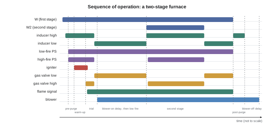
| Step | What should happen | If it does not, test |
|---|---|---|
| Standby | Board powered, normal light, chain closed, pressure switch open, no flame | 24 V at R and C, fuse, chain, pressure switch, flame-with-no-call code |
| Call for heat | R to W closes | Voltage at W; thermostat and cable |
| Inducer starts | Inducer runs at ignition speed | 120 V at inducer terminals; inducer motor |
| Draft proved | Pressure switch closes | Manometer at switch; hose, inducer, vent, condensate |
| Igniter warm-up | Igniter glows after pre-purge | Voltage at igniter plug; igniter resistance |
| Trial for ignition | Gas valve opens, burners light | 24 V at valve; inlet and manifold pressure; igniter position |
| Flame proved | Igniter turns off; burner stays lit | Flame signal in microamps; ground; polarity |
| Blower on | Blower starts after its delay | 120 V at blower speed tap; motor, capacitor |
| Steady state | Burner and blower run until call ends | Limit, rollout, pressure switch, flame signal during run |
| End of call | Valve closes, post-purge, blower-off delay | Valve closing; board timing; flame-with-no-call code |
The troubleshooting method
GAS-130 set out a ten-step method for electrical troubleshooting. The same method, applied to the sequence, is how a gas technician works on any appliance. First, gather the facts: talk to the customer about what happened and when, look at what has changed in the house, and read and record the board's fault history before anything is reset. Second, check the basics: power at the furnace, gas at the appliance valve, the thermostat calling, the filter, the burner and blower doors in place, and the vent and intake terminations clear. Many calls end here.
Third, watch the sequence, with the doors in their normal positions as far as possible and the sight opening used to view the flame, and note the time of each step with a watch or phone. The step where the sequence stops or goes wrong is the most important fact on the call. Fourth, form a hypothesis about what could make that step fail, using the lessons in this course. Fifth, test the inputs and outputs of that step with the right instrument, a meter, manometer, microamp reading or combustion analyzer, and confirm or reject the hypothesis. Sixth, find the root cause: not just the part that failed, but why it failed, as the dragging inducer in lesson 9 showed. Seventh, repair with the right part and method. Eighth, verify: run several complete cycles, every stage, and confirm the safety controls work. Ninth, record the readings and what was done, as found and as left. And tenth, explain to the customer, in plain words, what was wrong and what was done.
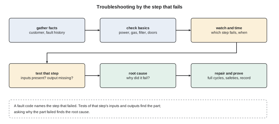
When a fault lies somewhere in a long chain of switches or wires, half-splitting, which GAS-130 introduced, saves time: test in the middle of the chain first, then in the middle of whichever half holds the fault, and so on.
Worked problem
How many readings does half-splitting need?
A boiler's safety chain has eight devices in series, and one of them is open. Testing one device at a time from the start of the chain could take up to eight readings. How many readings does half-splitting need at most?
Show solution
- Each reading halves the part of the chain that could hold the fault:
- \[8 \to 4 \to 2 \to 1\]
- That is three halvings:
- \[2^3 = 8\]
Answer: Half-splitting finds the open device in at most three readings instead of up to eight. On a short furnace chain of two or three switches the saving is small, but on a boiler with a long string of controls, or on a long run of wiring, it is large.
Sequences on other appliances
Boilers, water heaters and other appliances follow the same pattern with their own steps. A power-vented water heater's control, when its thermostat calls, starts the blower, waits for its pressure switch to close, runs a purge, then lights the burner by hot surface or spark and proves the flame; it has no circulating blower, so its steady state lasts until the water reaches its setting, followed by a post-purge. An atmospheric boiler with intermittent pilot ignition may first open a motorized vent damper and wait for its end switch to prove the damper open, then light the pilot, prove it, open the main valve, and start or keep running its circulator under the control of its operating aquastat. A condensing boiler with a modulating burner adds a fan speed check and a firing rate that rises and falls with the load. In every case the maker's sequence of operation, printed in the instructions and often summarized on the appliance, is the map, and the troubleshooting method is the same: find the step that fails, then test what that step needs.
Intermittent faults
The hardest faults are the ones that do not happen while the technician is there. For those, the fault history is the starting point, and the conditions under which the fault happens are the next clue: only on cold mornings, only on windy days, only on long runs, only on the first call of the day, only when the dryer or the range hood is running, only after the air conditioning has been on. Each condition points toward a cause. Cold weather affects vents, condensate and gas pressure; wind affects terminations; long runs heat up inducers and fill sagging vent pipes with condensate; exhaust appliances depressurize the house. Lesson 12 follows a whole intermittent case from start to finish.
The call in Rosedale
Jonah began by reading the board's history, which showed eleven codes, all the same: flame lost after ignition. He checked the basics and found nothing wrong. Then he set the thermostat to call and watched the sequence through the sight opening, calling out times while Rosa wrote them down. The inducer started at 0 seconds, the pressure switch closed at 3, the igniter glowed at 20, the gas valve opened at 37 and the burners lit at 38, all four across the row. The igniter went off. At 68 seconds the blower started. At 71 seconds the flames, which had been steady and blue, suddenly lifted and swirled, and at 72 the board shut the gas valve. The inducer ran on for its post-purge, and the board began again.
Worked problem
What the times show
From Jonah's notes, the burners lit at 38 seconds, the blower started at 68 seconds and the flame was lost at 72 seconds. How long after flame did the blower start, and how long after the blower started was the flame lost?
Show solution
- Blower-on delay:
- \[68 - 38 = 30 \text{ s}\]
- Time from blower start to flame loss:
- \[72 - 68 = 4 \text{ s}\]
Answer: The blower started on its normal 30-second delay, and the flame was lost four seconds later, every time. The flame was fine with the blower off and failed within seconds of it starting. Something about the blower was disturbing the flame, and on a furnace the most serious explanation is air from the blower reaching the combustion side through a cracked heat exchanger.
Jonah looked over his shoulder. Rosa nodded. A dirty flame rod or a poor ground would weaken the signal at all times, not only once the blower ran, so he did not start there. He put his meter in series with the flame rod and watched it through a full cycle: from the moment the burners lit until the blower started, the signal read a steady 2.8 microamps, a healthy figure; within seconds of the blower starting, it fell to almost nothing as the flames lifted. With Rosa's permission he ran a combustion analyzer probe into the flue: with the blower off, the flue gas carbon monoxide was low; within seconds of the blower starting, it climbed sharply before the board shut the valve.
Rosa then shut the furnace off at its disconnect and its gas valve, and they pulled the burners. With an inspection camera, Jonah found a crack about 40 mm long in the second heat exchanger section, near a bend, and a pattern of soot around it. A cracked heat exchanger is an immediate hazard under Ontario's rules: the furnace was left off, tagged as TSSA's procedures require, and the owner was told plainly why. Rosa set up two electric heaters in the house, and Hank booked a visit later in the month to quote a replacement.
On the drive back Rosa told Jonah what she had seen him do right. He had not replaced the flame rod, which would have been a natural guess from the code, and which would have left a family with a cracked heat exchanger and a furnace that "worked better" for a while. He had found the exact step and the exact moment, asked what could connect them, and tested until he knew. "The code said flame lost," she said. "It was true. It just wasn't the whole story. The sequence told you the rest."
Proving the repair
Every repair ends with proof that the whole system works, not just the part that was replaced. The technician runs at least several complete cycles, through every stage the appliance has, and watches each step happen on time. The pressures, the temperature rise and the flame signal are measured and recorded. Where the instructions allow it, the safety controls are proved: the board's response to an open limit circuit or a disconnected pressure switch hose, tested with the burner off or as the instructions direct, and the burner's shutdown when the call ends. The fault history is cleared, so that any return of the fault will be recorded cleanly. And the customer is told what was found, what was done and what to watch for.
Common mistakes
MistakeStarting with the part the fault code names.
InsteadWatch the sequence first and find the exact step and moment it fails.
MistakeResetting the board before reading the fault history.
InsteadRead and record the history first.
MistakeStopping at the failed part without asking why it failed.
InsteadFind the root cause, or the fault will return.
MistakeProving only the repaired part.
InsteadRun complete cycles on every stage and check the safety controls.
MistakeIgnoring when an intermittent fault happens.
InsteadThe conditions, such as cold, wind or long runs, point to the cause.
Summary and key terms
- A typical two-stage induced-draft furnace runs a fixed sequence: standby checks; a call for heat; inducer start; pressure switch proof; pre-purge; igniter warm-up; gas valve opening and trial for ignition; flame proof; blower-on delay; steady state with continuous safety checks; second stage when called; and at the end of the call valve closing, post-purge and blower-off delay.
- Each step has its own tests.
- Bayline's method is to gather the facts and fault history, check the basics, watch the sequence and time each step, form a hypothesis, test the step's inputs and outputs, find the root cause, repair, verify complete cycles and safety controls, record and explain.
- Half-splitting speeds the search along a chain.
- Intermittent faults are traced through the history and the conditions under which they happen.
- A fault code names the failed step, not the whole story.
- Sequence of operation
- The fixed order of steps an appliance's control carries out from a call for heat to standby.
- Standby
- The idle state in which the board waits for a call and keeps checking its inputs.
- Steady state
- The part of the cycle in which the burner and blower run normally.
- Blower-off delay
- The time the blower keeps running after the burner shuts off, to recover heat.
- Half-splitting
- Testing in the middle of a circuit to halve the section that could hold the fault.
- Root cause
- The underlying reason a part failed or a fault occurred.
- Intermittent fault
- A fault that comes and goes, often only under certain conditions.
Practice problems
Work each problem on paper first, then reveal the answer to check.
Which pressure switch condition does the board check in standby?
Show answer
That the switch is open.
Why time each step of the sequence?
Show answer
To find exactly which step fails and when, and what it coincides with.
A flame is fine until the blower starts and then fails within seconds. What serious cause must be checked?
Show answer
A cracked heat exchanger.
What does half-splitting do?
Show answer
Halves the part of a circuit that could hold the fault with each reading.
What ends every repair?
Show answer
Several complete cycles on every stage, safety checks, recorded readings and an explanation to the customer.
Lesson quiz · 5 questions
Score 60% or more to complete this lesson.
Create a free account to save your progress, take quizzes and earn a certificate.