
GAS-220 · Lesson 10 of 12 · 24 min
Reading appliance wiring diagrams
▶ Video coming soon A video version of this lesson is on the way.
On Thursday evening, November 12, after a long day at the Fairhaven start-up, Jonah sat at the shop table with Hank and three other apprentices and a photocopy of a wiring diagram the size of a placemat. It came from the inside of a furnace door, and it had two drawings on it: a crowded picture of the furnace's parts with coloured wires running between them, and a cleaner drawing of horizontal lines between two vertical rails. Hank tapped the second one. "Every furnace you'll ever work on has one of these glued inside its door," he said. "It is the most valuable piece of paper in the basement. If you can read it, you can troubleshoot a furnace you've never seen before. If you can't, you're replacing parts and hoping." He handed out highlighters. "Tonight we're going to follow the electricity."
GAS-130 introduced ladder diagrams with a practice furnace and showed how to test voltage from point to point. This lesson builds on it. It explains the two kinds of diagram found on appliances, the symbols and labels they use, how to trace a circuit through a control board, and how to use a diagram to choose test points when troubleshooting.
Two kinds of diagram
Most appliance diagrams come in two parts. The connection diagram, also called the wiring diagram or pictorial diagram, shows the parts roughly where they sit in the appliance, with every wire drawn from terminal to terminal and labelled with its colour. It answers the question "where is this wire, and what does it plug into?" It is the one to use when replacing a part or checking a connection, but it is hard to follow for logic, because wires cross and loop around the drawing.
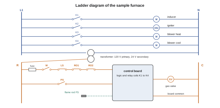
The schematic or ladder diagram ignores where the parts are and shows only how they are connected electrically. Two vertical lines, the rails, represent the power supply: on the line-voltage part of the diagram, usually L1 or hot on one side and neutral on the other; on the low-voltage part, usually R or 24 VAC on one side and C or common on the other. Each horizontal line, a rung, is one circuit: it starts at one rail, passes through the switches that control it, reaches its load, and ends at the other rail. By convention the switches are drawn on the side of the rung nearer the hot or R rail and the load nearer the neutral or common. It answers the question "what has to happen for this load to get power?"
Symbols and labels
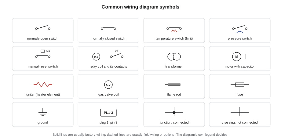
Diagrams use a fairly standard set of symbols, though every maker has its own style and a legend on the diagram explains them. A normally open switch is drawn with its contacts apart, and a normally closed switch with them touching or bridged; as GAS-130 stressed, normal means the switch's state at rest, not its state while the appliance runs. The kind of switch is shown by its symbol or a label: a temperature switch such as a limit or rollout often has a small zigzag or the letters for limit; a pressure switch has a small diaphragm or a label such as PS; a manual-reset switch may be marked MR or drawn with a button. A relay appears in two places: its coil, a circle or box with a label such as K1 or IND, and its contacts, a switch symbol with the same label, which may be on a completely different rung. A transformer is drawn as two coils side by side; a motor is a circle with an M, sometimes with its capacitor beside it; an igniter is often drawn as a resistor or heater element; the gas valve is shown as a coil, often labelled GV or MV; a flame rod is a small rod symbol or a label such as FS. A fuse has its own symbol, and ground is shown by a set of short lines or a ground sign.
The lines carry information too. A solid line is usually factory wiring and a dashed line is usually field wiring, installed on site, such as the thermostat cable, or an optional accessory; the legend says which. Where two lines cross without a dot, they are not connected; a dot at a crossing shows a connection. Wire colours are abbreviated, commonly BK for black, WH for white, RD for red, BL or BU for blue, YL for yellow, OR for orange, BR for brown and GN or GR for green. Plug connections are labelled with the plug and pin number, for example PL1-3 for pin 3 of plug 1, so that the technician can find the right pin to test. The diagram's notes often contain important rules, such as the wire temperature rating to use if any wire is replaced, a warning that polarity must be observed, or which blower speed tap is factory-set for heating.
| Label or abbreviation | Usual meaning | Where it appears |
|---|---|---|
| L1, N | Line (hot) and neutral | Line-voltage rails |
| R, C | 24-volt hot and common | Low-voltage rails |
| W, W2, Y, G | Heat, second-stage heat, cooling and fan calls | Thermostat terminals |
| LS, HL | High limit switch | Safety chain |
| RO, FRS | Flame rollout switch | Safety chain |
| PS, LPS, HPS | Pressure switch, low and high fire | Draft proving |
| IND, ID | Inducer | Line-voltage rung |
| HSI, IGN | Hot surface igniter | Line-voltage rung |
| GV, MV, HI | Gas valve, main valve, high fire | Low-voltage rung |
| FS, FR | Flame sensor or flame rod | Board input |
| PL1-3 | Plug 1, pin 3 | Connector pins |
Tracing a circuit
Reading a ladder diagram is a habit more than a skill. The technician starts at the power source, the line-voltage supply and the transformer, then reads each rung from the hot side to the neutral side, asking for each load: what has to close for this to get power? On a furnace the answer usually involves both the physical switches drawn on the rung and the board's relays. A relay's coil is energized by the board's logic, so the board is drawn as a block with its relays inside, and the diagram shows which board terminal each relay contact powers. The legend or a cross-reference number on the coil tells where its contacts are.
The low-voltage part of a furnace diagram usually shows the safety chain clearly: R from the transformer passes through the fuse, then the high limit and the rollout switches in series, and returns to a board input, often marked with the limit's name. The pressure switch is drawn on its own pair of board terminals. The gas valve is drawn between a board output and C. Following the chain with a highlighter is the quickest way to learn which switches a particular furnace has, and in what order, which is exactly what is needed to troubleshoot it.
Worked problem
What must close to open the gas valve?
On the sample ladder diagram, list every switch and condition that must be satisfied before the board powers the gas valve on a call for heat.
Show solution
- Follow the low-voltage circuit from R:
- 1. The transformer is powered and its secondary feeds R through the 3 A fuse.
- 2. The thermostat closes R to W.
- 3. The high limit is closed.
- 4. Both rollout switches are closed.
- 5. The board has seen the pressure switch open before the inducer started, and closed after it.
- 6. The board has completed its pre-purge and igniter warm-up.
- Then the board powers the gas valve and must see flame on its flame sense terminal within the trial for ignition.
Answer: Seven conditions stand between the call for heat and gas at the burner, and each one has its own place on the diagram, its own test point and its own fault code. Writing them down for an unfamiliar furnace before testing it is the habit Hank wanted the apprentices to form.
Using the diagram to choose test points
Once the circuit is traced, the diagram tells the technician where to put the meter. GAS-130 described two methods. In point-to-reference testing, one lead stays on the reference, C for low-voltage circuits or neutral for line-voltage circuits, and the other moves along the rung, terminal by terminal, from the hot side toward the load. Voltage is present up to the point where the circuit is open, and missing after it. In voltage-drop testing, the leads go across one switch at a time: a closed switch carrying current shows close to zero volts across it, and an open switch shows the full supply voltage across it. Both methods find the open switch without disconnecting anything, and both depend on the diagram to know which terminal comes next.
Worked problem
Finding the open switch
A furnace shows the sample board's code for an open limit circuit. With the thermostat calling and the meter's common lead on C, Jonah measures from C to each point along the safety chain, in order: R at the fuse, 24.6 V; the input side of the high limit, 24.6 V; between the high limit and the first rollout switch, 24.6 V; between the first and second rollout switches, 0 V; at the board's limit input, 0 V. Where is the open?
Show solution
- Voltage is present up to and including the point between the high limit and the first rollout switch, so the high limit is closed:
- \[24.6 \text{ V before and after the high limit}\]
- Voltage is missing after the first rollout switch:
- \[24.6 \text{ V} \to 0 \text{ V across rollout switch 1}\]
- A voltage-drop reading across that switch alone would show the full 24.6 V.
Answer: The first rollout switch is open. It is a manual-reset switch, and lesson 8 explained that an open rollout switch is evidence of flame escaping the burner area. Jonah would not simply press its reset button: he would inspect the burners, heat exchanger and vent, and check for the cause, before resetting it and watching several ignitions.
The diagram is also the guide when a reading does not make sense. If the meter shows 24 volts at a board's gas valve output but the valve does not open, the diagram shows whether there is a plug between the board and the valve, and which pins to test next. If a load runs when it should not, the diagram shows which relay contact feeds it, and so which board output to check. On a two-stage or variable-speed furnace, the diagram shows how the board decides between stages and which wires carry the signal to the blower.
When the diagram is missing or wrong
Old furnaces sometimes have lost their diagram, or have a faded one that cannot be read, and some have been rewired by someone who did not follow it. The maker's literature, often available from the maker's website or the distributor by model number, usually includes the diagram, and Bayline keeps a library of the ones its technicians download. If no diagram can be found, the technician draws one: tracing each wire from terminal to terminal with the power off, writing down its colour and its ends, and turning the result into a ladder. That takes time, but it is the only safe way to work on an unfamiliar control circuit. A wiring diagram that does not match the appliance is a warning that someone has modified it, and every difference is checked against the maker's diagram for that model before the appliance is put back in service.
When a technician replaces a part, the wiring goes back exactly as the diagram shows. Spare blower leads go on the parking terminals, not taped and left loose. Any wire that has to be replaced is replaced with wire of the same gauge and of the temperature rating the diagram's notes specify, commonly 105 °C, because the inside of a furnace runs hot. Splices are made with the right connectors, never with tape alone.
What Jonah took away
By the end of the evening the apprentices' photocopies were covered in colours: yellow for the 120-volt circuits, orange for the 24-volt safety chain, green for the gas valve rung and blue for the blower. Hank had each of them answer three questions for the furnace on the diagram: what must close for the gas valve to open; where would you put the meter to find an open rollout switch; and which relay powers the blower in heating. Then he gave them a second diagram, from a different maker, and had them answer the same three questions in ten minutes. "Different drawing, same furnace," he said when they had finished. "They all do the same things in the same order. The diagram just tells you where."
Common mistakes
MistakeTroubleshooting from the connection diagram alone.
InsteadUse the ladder diagram to see what must close for each load.
MistakeTreating normally open as open while running.
InsteadNormal means at rest; check what the switch does in operation.
MistakeAssuming two crossing lines are connected.
InsteadOnly a dot at a crossing shows a connection.
MistakeTaping up spare blower speed leads loose in the cabinet.
InsteadPut them on the parking terminals as the diagram shows.
MistakeReplacing a furnace wire with ordinary building wire.
InsteadUse the gauge and temperature rating the diagram's notes specify.
Summary and key terms
- Appliance diagrams usually have a connection diagram, showing parts in place with wire colours and terminals, and a ladder diagram, showing the circuits as rungs between two rails, L1 and neutral for line voltage and R and C for 24 volts, with switches toward the hot side and loads toward the neutral.
- Symbols show normally open and closed switches, temperature and pressure switches, relay coils and their contacts with matching labels, transformers, motors, igniters, valves, flame rods, fuses and ground; solid lines are usually factory wiring, dashed lines field wiring, and only a dot shows a connection.
- The diagram's notes give rules such as wire temperature ratings.
- Trace each load back to the switches and relays that power it, write down the conditions for the gas valve, then choose test points for point-to-reference or voltage-drop testing.
- When a diagram is missing, get the maker's diagram or draw one, and always rewire exactly as the diagram shows.
- Connection diagram
- A diagram showing the parts in their physical positions with every wire and its colour.
- Ladder diagram
- A schematic showing each circuit as a rung between two supply rails.
- Rail
- One of the two vertical supply lines of a ladder diagram.
- Rung
- One horizontal circuit of a ladder diagram, from rail to rail through switches to a load.
- Field wiring
- Wiring installed on site, often shown dashed, such as the thermostat cable.
- Parking terminal
- A board terminal for holding unused blower speed leads.
- Point-to-reference testing
- Testing with one meter lead on a fixed reference and the other moving along the circuit.
Practice problems
Work each problem on paper first, then reveal the answer to check.
What question does a ladder diagram answer best?
Show answer
What has to close for each load to get power.
How is a relay shown on a ladder diagram?
Show answer
Its coil on one rung and its contacts, with the same label, on another.
What does a dot where two lines cross mean?
Show answer
The wires are connected; without a dot they are not.
What does a full 24 volts measured across one closed-looking switch in the chain mean?
Show answer
That switch is open.
What wire is used to replace a furnace wire?
Show answer
The gauge and temperature rating the diagram's notes specify, often 105 °C.
Lesson quiz · 5 questions
Score 60% or more to complete this lesson.
Create a free account to save your progress, take quizzes and earn a certificate.