
GAS-220 · Lesson 3 of 12 · 23 min
Gas valves and their parts
▶ Video coming soon A video version of this lesson is on the way.
Hank Morrow keeps a shelf in the shop for parts that have failed in interesting ways, and on the evening of Thursday, October 22, he took down three gas valves for the apprentice class. One was an old standing-pilot combination valve, cut in half on the bandsaw so its passages showed. One was a modern furnace valve with two terminals and a two-stage regulator. The third had come out of a furnace the week before, after a call where everything upstream had checked out and the valve simply would not open. "The gas valve is the last word," Hank said. "Every switch in the safety chain, every check on the board, ends in two wires on this thing. When it's powered, gas flows. When it isn't, gas has to stop, every time, for twenty years. Learn what's inside it, and you'll know what you can adjust, what you can test and what you never touch."
This lesson describes the combination gas valve found on almost every residential gas appliance: what its parts do, how the different types of valve match the different ignition systems, how the regulator inside it sets the burner's pressure, and how a technician tests, adjusts and replaces one. Lesson 2 covered the pilot safety in a standing-pilot valve; this lesson covers the rest of the valve and its electronic relatives.
One body, several jobs
Older appliances had a row of separate parts in their gas train: a manual valve, a pilot safety, a regulator and a solenoid valve. A combination gas valve puts these into one body bolted to the manifold. Following the gas from inlet to outlet, a typical valve has an inlet screen that catches scale and debris; a manual control, usually a knob or a switch marked on and off, and on standing-pilot valves a pilot position; on standing-pilot valves, the pilot safety held by the thermocouple; one or two automatic valve operators, which open when their coils are powered; a servo pressure regulator, which holds the outlet pressure steady whatever the inlet pressure does; a pilot outlet where the appliance has a pilot; and pressure taps on the inlet and outlet for a manometer.
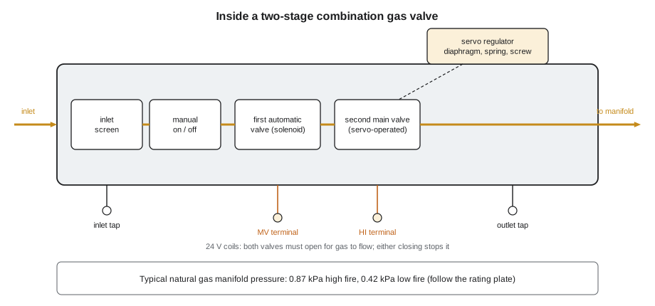
The two automatic valves in series are the valve's redundancy, which lesson 1 introduced. The product standards for most residential appliances require two independent means of shutting off the main burner gas, so that a particle of scale under one seat or a sticking plunger in one operator cannot leave gas flowing to an unlit burner. On many valves the first is a simple solenoid valve and the second is the regulator's own main valve, opened and closed by the servo system. Both must open for gas to flow, and either one closing stops it.
Valves for each ignition system
Gas valves are built to match the ignition system they serve, and a valve from one family cannot be substituted for another. A standing-pilot combination valve has a thermocouple connection and a pilot outlet, and its main valve is operated by 24 volts from the thermostat, or, on a millivolt valve, by the thermopile's own output. An intermittent pilot valve, used with the systems in lesson 4, has two operators and usually three terminals, often marked PV for the pilot valve, MV for the main valve and MV/PV as their common: the ignition module powers the pilot valve first, and the main valve only after the pilot flame has been proved. A direct ignition valve, used with the hot surface and spark systems in lesson 5, has no pilot outlet: the board powers its operators together and the gas goes straight to the main burner.
Many modern valves also control the burner's firing rate. A two-stage valve has a third terminal, often marked HI, and two regulator adjustments: one for low fire, and one for high fire when the HI terminal is powered. A modulating valve varies its outlet pressure over a range, driven by a signal from the control board or by a small stepper motor, so that the burner's input can follow the heat load. Many valves are also slow-opening or step-opening: they open to a low pressure for the first moment of ignition, then rise to full pressure, so that the burner lights softly instead of with a thump.
| Valve type | Used with | Typical terminals | Main features |
|---|---|---|---|
| Standing-pilot combination | Standing pilot and thermocouple | Thermocouple socket; 24 V main valve terminals | Manual pilot position, pilot safety magnet |
| Millivolt | Standing pilot and thermopile | Thermopile and switch terminals | Needs no house power |
| Intermittent pilot | IPI module | PV, MV/PV, MV | Pilot opened first; main only after pilot is proved |
| Direct ignition | Hot surface or direct spark | Two terminals (MV and common) | No pilot outlet; often slow-opening |
| Two-stage | Two-stage furnaces | MV, common, HI | Separate low-fire and high-fire adjustments |
| Modulating | Modulating furnaces and boilers | Power plus a control signal | Outlet pressure varies over a range |
The servo regulator
The regulator inside a combination valve is the part a technician adjusts most often. It works on the same principle as the service regulators GAS-120 described: a diaphragm feels the outlet pressure, a spring pushes against it, and the balance between them positions a valve that lets just enough gas through to hold the outlet pressure at its setting. In a servo regulator the diaphragm does not move the main valve directly. It controls a small bleed of gas that in turn moves the main valve, so a small, sensitive diaphragm can control a large flow precisely. The adjustment is a screw under a sealing cap; turning it compresses or relaxes the spring and raises or lowers the outlet pressure.
The regulator setting is the manifold pressure, and it is not a matter of preference. The appliance's rating plate and instructions give it, and the burner orifices were sized for it. On a typical natural gas furnace it is about 0.87 kPa at high fire, and on a two-stage furnace about 0.42 kPa at low fire; on propane it is much higher, commonly around 2.5 kPa, with a different regulator spring supplied in the conversion kit. A regulator can only reduce pressure, so it cannot make up for an inlet pressure that is too low. The valve's instructions give the minimum inlet pressure it needs to regulate properly, and GAS-120 showed how pipe sizing keeps the inlet pressure above it.
Worked problem
What a low manifold pressure does to the input
A furnace's plate gives an input of 26 kW at a manifold pressure of 0.87 kPa. Jonah measures 0.77 kPa at high fire. The flow through a fixed orifice varies with the square root of the pressure across it. About what input is the furnace firing at?
Show solution
- Ratio of the flows:
- \[\sqrt{\frac{0.77}{0.87}} = \sqrt{0.885} = 0.941\]
- Actual input:
- \[26 \text{ kW} \times 0.941 \approx 24.5 \text{ kW}\]
Answer: The furnace is underfiring by about 1.5 kW, about 6 parts in 100. Before adjusting the regulator, Jonah checks the inlet pressure while the furnace runs: if the inlet is too low, the fault is in the supply, not the valve. If the inlet is good, he sets the manifold pressure to 0.87 kPa and confirms the input by clocking the meter, as GAS-210 showed.
Worked problem
Low fire on a two-stage valve
A two-stage furnace fires 26 kW at 0.87 kPa on high fire. Its low-fire manifold pressure is set to 0.42 kPa. About what is its low-fire input, and what fraction of high fire is it?
Show solution
- Ratio of the flows:
- \[\sqrt{\frac{0.42}{0.87}} = \sqrt{0.483} = 0.695\]
- Low-fire input:
- \[26 \times 0.695 \approx 18.1 \text{ kW}\]
Answer: Low fire is about 70 parts in 100 of high fire. That is typical: the low-fire pressure is roughly half the high-fire pressure, but because flow follows the square root, the input falls by only about 30 parts in 100. The plate gives both inputs, and clocking the meter on each stage confirms them.
Pressure taps and manometer readings
The inlet and outlet pressure taps are small threaded ports closed by a screw or a plug, and they are where the technician connects a manometer. The inlet tap reads the supply pressure reaching the valve, and is checked both with the appliance off, the static pressure, and with it and every other gas appliance in the house running, the running pressure. The outlet tap reads the manifold pressure the regulator is delivering. On many valves the outlet tap must be read with the regulator's vent or the burner box in its normal condition, because a sealed combustion furnace's regulator may be referenced to the burner box pressure. The appliance instructions say how to connect the manometer for that model.
Every opened tap is a potential leak. After the readings, the screw is put back and snugged, not forced, and the tap is leak tested with the burner running, using a leak detection solution or an electronic detector. At Bayline, the readings go on the service record with the as-found and as-left values.
Testing the valve electrically
When the board calls for gas and nothing happens, the valve is tested the same way as any other load, with the point-to-reference method GAS-130 taught. With the meter on AC volts, one lead goes on the valve's common terminal and the other on its main valve terminal while the board is in its trial for ignition. If about 24 volts is present and the inlet pressure is good, the valve has been told to open and has not: the valve is faulty. If no voltage is present, the valve is not the problem; something upstream, the board or a switch in the chain, has not powered it. On a two-stage valve the HI terminal is checked the same way during a call for high fire.
With the power off and the wires removed, the valve's coils can also be checked for continuity. An open coil reads infinite resistance, OL on the meter, and means the valve must be replaced. A coil that reads very low compared with the maker's figure may be shorted and can blow the board's fuse. Bayline technicians do not tap a sticking valve with a screwdriver handle to make it open, because a valve that sticks once will stick again, and a valve that sticks open is far more dangerous than one that sticks shut.
Replacing a gas valve
A gas valve is replaced only with the part the appliance maker specifies, or with a replacement the valve maker lists for that application, matched for gas type, capacity, number of stages, opening characteristic, voltage and ignition system. Universal replacement valves come with instructions and adapters that must be followed exactly. Before the old valve comes out, the gas is shut off at the appliance's manual valve and the power is off. The valve is held with a wrench on its body flats, never by its top, and pipe sealant goes on the male threads only, so none can be pushed into the valve's inlet. The new valve's inlet screen is left in place.
After installation the joints are leak tested, the manifold pressure is set to the plate on each stage, the input is clocked, and the full sequence is checked, including that the valve closes promptly when the call ends. The valve that Hank had on his shelf had come out of a 2004 furnace in Dundas on Tuesday, October 13. The board had shown 24.3 volts across its terminals during three trials for ignition, the inlet pressure was normal, and the valve's coil read OL. Rosa replaced it with the maker's listed replacement, set the manifold pressure, clocked the input and watched three complete cycles before she left.
What a technician never does to a gas valve
A technician never adjusts a regulator to cure a problem somewhere else, such as turning up the manifold pressure to make a weak flame look better or to raise a low temperature rise; the cause is found instead. A technician never removes or modifies the regulator's sealing cap beyond what the instructions allow, never drills or alters a passage, and never converts a valve to another gas without the maker's kit. A valve that has been under water in a flood, has been dropped, has a damaged body or leaks externally is replaced, not repaired. And a valve is never repaired internally in the field: the parts that make it safe are sealed at the factory for a reason.
Common mistakes
MistakeTurning up the manifold pressure because the flame looks weak.
InsteadFind the cause: low inlet pressure, dirty orifices or a combustion air problem.
MistakeConcluding the valve is bad because the burner did not light.
InsteadCheck for 24 volts at the valve during the trial and for good inlet pressure first.
MistakeUsing thread sealant on the valve's female threads.
InsteadApply sealant to male threads only, so none enters the valve.
MistakeFitting any valve that fits the manifold.
InsteadUse the maker's specified or listed replacement for that appliance and gas.
MistakeLeaving a pressure tap screw loose after testing.
InsteadClose it and leak test it with the burner running.
Summary and key terms
- A combination gas valve combines an inlet screen, a manual control, on some valves a pilot safety, two automatic valves in series, a servo pressure regulator, a pilot outlet where needed, and inlet and outlet pressure taps.
- The two automatic valves give redundancy.
- Valves are matched to their ignition system: standing pilot, millivolt, intermittent pilot or direct ignition, and may be two-stage, modulating or slow-opening.
- The regulator holds the manifold pressure set on the rating plate, about 0.87 kPa at high fire and 0.42 kPa at low fire on typical natural gas furnaces, and cannot correct a low inlet pressure.
- Input varies with the square root of manifold pressure.
- A valve with 24 volts on its terminals and good inlet pressure that does not open is faulty.
- Replacements must be the maker's specified or listed part, set up and checked fully after installation.
- Combination gas valve
- A single valve body combining manual, safety, regulating and automatic valve functions.
- Automatic valve operator
- The coil-operated part of a gas valve that opens when powered.
- Servo regulator
- A regulator in which the diaphragm controls a small bleed that positions the main valve.
- Manifold pressure
- The gas pressure delivered to the burner orifices, set by the valve regulator.
- Inlet screen
- A fine screen at a valve inlet that catches scale and debris.
- Two-stage valve
- A gas valve with separate low-fire and high-fire outlet pressure settings.
- Modulating valve
- A gas valve whose outlet pressure varies over a range on a control signal.
- Slow-opening valve
- A valve that opens to a low pressure first so the burner lights softly.
Practice problems
Work each problem on paper first, then reveal the answer to check.
Why does a combination valve have two automatic valves in series?
Show answer
So that gas stops even if one of them fails to seal: redundancy.
Can a gas valve's regulator make up for a low inlet pressure?
Show answer
No; a regulator can only reduce pressure.
What does 24 volts across the valve terminals with good inlet pressure and no gas flow mean?
Show answer
The valve has been powered and has not opened, so the valve is faulty.
What are the PV and MV terminals on an intermittent pilot valve?
Show answer
The pilot valve and main valve operators.
Where does thread sealant go when a valve is installed?
Show answer
On the male threads only.
Lesson quiz · 5 questions
Score 60% or more to complete this lesson.
Create a free account to save your progress, take quizzes and earn a certificate.