
ELEC-320 · Lesson 9 of 12 · 25 min
Ground-fault protection and system grounding methods
Ground faults are the most common type of fault in electrical systems: insulation breaks down, a conductor rubs through against a cable tray, moisture enters a motor, or a tool slips in a panel. In a solidly grounded system, a bolted ground fault draws enough current to trip the overcurrent device quickly. Many ground faults, however, are arcing faults, with an arc in series with the fault path that limits the current to a fraction of the bolted value. On large 347/600 V and 277/480 V services, an arcing ground fault may draw several hundred to a few thousand amperes, too little to trip a 2000 A or 3000 A main breaker promptly, but more than enough to burn through switchgear in seconds. Ground-fault protection of equipment was introduced into the codes in the early 1970s after a series of destructive switchgear burndowns. This lesson covers how arcing ground faults behave, ground-fault protection requirements and methods, zone selective interlocking and coordination of ground-fault devices, and the alternatives of ungrounded and high-resistance grounded systems.
Why arcing ground faults are dangerous
The voltage needed to sustain an arc is roughly 100 to 150 V regardless of current. On a 120/208 V system, with only 120 V to ground, an arc to ground tends to extinguish itself at each current zero and is difficult to sustain. On a system with 277 V or 347 V to ground, the arc restrikes easily after each current zero and becomes self-sustaining. The arc voltage and the impedance of the arc path reduce the fault current, often to 20 % to 40 % of the bolted fault current, and sometimes much lower. A main breaker's long-time element might take minutes to trip at those currents, or never trip at all if the fault current is below its pickup. Meanwhile the arc releases enormous energy, vaporizing copper and spreading along the bus. This is why ground-fault protection is required on large solidly grounded systems with more than 150 V to ground.
Code requirements
In Canada, CEC Rule 14-102 requires ground-fault protection to de-energize all normally ungrounded conductors of a faulted circuit for solidly grounded circuits of more than 150 V to ground and less than 750 V phase-to-phase, where the overcurrent device is rated 1000 A or more. The maximum setting is 1200 A, with a maximum time delay of 1 s for ground-fault currents of 3000 A or more. Protection is required for service and feeder circuits meeting these conditions, with exceptions for fire pumps and some continuous processes where an orderly shutdown is needed.
The protection is often called GFP or GFPE (ground-fault protection of equipment) to distinguish it from GFCI personnel protection, which trips at about 5 mA. GFP protects switchgear and conductors from burndown; it does not protect people from shock.
Methods of sensing ground faults
- Residual sensing: current sensors on each phase (and the neutral in a four-wire system) feed the trip unit, which adds the currents vectorially. In a healthy circuit the sum is zero; any residual is current returning by another path, that is, ground-fault current. Most electronic trip units in power circuit breakers use residual sensing with an external neutral sensor.
- Zero-sequence sensing: a single core-balance current transformer surrounds all phase and neutral conductors; it produces an output only when their sum is not zero. It is used with switches and relays and for sensitive ground-fault detection on feeders and motors.
- Ground-return sensing: a current transformer on the main bonding jumper measures current returning from the bonding system to the neutral. It is simple but works only at the service with a single source.
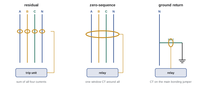
The neutral sensor is critical. In a four-wire system, unbalanced line-to-neutral loads return on the neutral; if the neutral sensor is omitted, misplaced or connected backwards, the trip unit sees the neutral current as a ground fault and trips under normal load, or fails to see a real fault. Neutral-to-ground connections downstream of the GFP sensor (Lesson 8) create the same problem: some neutral current returns on the bonding path and looks like a ground fault, and some ground-fault current returns on the neutral and is masked. Many nuisance GFP trips are traced to these wiring errors.
Coordination of ground-fault protection
Ground-fault protection on a main breaker with no ground-fault protection on downstream feeders can cause a total outage for a ground fault on a small branch circuit: the fault current flows through the main's GFP sensor and trips the main before the branch breaker opens. To limit outages, specifications often call for ground-fault protection on feeders as well, with the main set at a higher pickup and longer delay so that each level trips before the next one upstream. Ground-fault curves are plotted on the time-current coordination study alongside phase curves (Lesson 6). Zone selective interlocking (ZSI) allows the upstream device to trip with no intentional delay when a fault is in its own zone, while still waiting for downstream devices that report seeing the fault; this both improves selectivity and reduces arc flash energy.
Worked problem
Setting ground-fault protection
A 3000 A, 347/600 V main breaker and 800 A feeder breakers all have GFP. The main has a maximum allowed setting of 1200 A. Propose pickups and delays that coordinate and meet the CEC limits.
Show solution
- Feeders: set pickup at 400 A (half the breaker rating) with a short delay of 0.1 s, so they trip first for faults on their circuits.
- Main: set pickup at 1200 A (the maximum allowed) with a delay of 0.3 s, giving a clear time band above the feeders.
- Check the main's delay: at 3000 A ground-fault current, it must trip in no more than 1 s; 0.3 s meets this.
- Plot both curves on the coordination study and confirm the bands do not overlap, including breaker clearing times. Consider ZSI so the main can trip faster for faults on its own bus.
Answer: Feeders at 400 A and 0.1 s; main at 1200 A and 0.3 s, coordinated and within the code limits. Test both settings by primary or secondary injection during commissioning.
GFP must be performance-tested when first installed, typically by primary current injection through the sensors or by the manufacturer's test procedure, and the results recorded and kept for the inspector. Testing confirms polarity of the neutral sensor, correct settings, and that the breaker actually opens.
Ungrounded systems
An ungrounded system has no intentional connection between the system conductors and earth: a delta-connected 600 V or 480 V supply with no grounded phase or neutral, common in older industrial plants. Its main advantage is continuity of service: the first ground fault does not cause a large current, because there is no return path except the distributed capacitance of the system to earth, so the process keeps running. Its disadvantages are serious:
- The first fault goes undetected unless ground detectors are installed and monitored, and it raises the voltage to ground of the other two phases to full line voltage.
- A second fault on a different phase creates a phase-to-phase fault through the bonding system, which may occur at two separate locations and cause equipment damage at both.
- Intermittent or arcing ground faults can cause transient overvoltages of several times normal, due to charging and discharging of the system capacitance, stressing insulation throughout the system.
In Canada, the CEC requires ungrounded systems to have ground detection devices that indicate the presence of a ground fault, and requires the equipment and enclosures to be bonded just as in grounded systems.
High-resistance grounding
High-resistance grounding (HRG) combines the continuity of an ungrounded system with the stability and fault location of a grounded one. A resistor is connected between the wye neutral of the source and ground (or, for a delta source, between an artificial neutral created by a zig-zag or grounding transformer and ground). The resistor is sized to limit ground-fault current to a low value, typically 1 to 10 A on low-voltage systems, slightly more than the system's capacitive charging current so that transient overvoltages are suppressed.
- On the first ground fault, current is limited to the resistor value, which is too little to cause damage or an arc flash; the system keeps running, and an alarm alerts maintenance staff.
- A pulsing contactor varies the resistor value, creating a pulsing ground current that can be traced with a clamp-on meter to the faulted feeder and load, so the fault can be located and repaired at a convenient time.
- A second fault on another phase is a phase-to-phase fault, so feeder relays or alarms should prompt quick repair of the first fault.
- Line-to-neutral loads are not permitted on an HRG system, because the neutral is not solidly grounded; 120 V loads are served from separate transformers with solidly grounded secondaries.
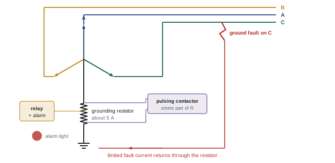
In Canada, the CEC permits impedance grounding of systems where conditions such as qualified maintenance and ground-fault detection are met, and does not permit line-to-neutral loads on these systems.
HRG is widely used in continuous process industries such as pulp and paper, mining, petrochemical and data centres. Converting an existing ungrounded system to HRG requires an artificial neutral, careful checking that no line-to-neutral loads exist, and updated labelling and maintenance procedures.
Comparing system grounding methods
| Method | First ground fault | Line-to-neutral loads | Typical use |
|---|---|---|---|
| Solidly grounded | High current; trips overcurrent device or GFP | Yes | Commercial buildings, 120/208 V and 347/600 V or 277/480 V |
| Ungrounded | Tiny capacitive current; continues running | No | Older industrial plants |
| High-resistance grounded | Limited to a few amperes; alarms | No | Continuous process industries |
| Low-resistance grounded | Limited to hundreds of amperes; trips | No | Medium-voltage industrial systems |
Ground-fault protection in existing buildings
In existing buildings, ground-fault protection systems may have been installed decades ago and never tested since. Older electromechanical relays and sensors may have drifted, wiring may have been altered, and downstream panels may have acquired neutral-to-ground connections through renovations. A program of periodic GFP testing, along with checks of neutral and bonding conductors for current, helps ensure the protection will work when needed and will not trip unnecessarily. Where nuisance tripping has led staff to raise settings or disable GFP, the root cause must be found and corrected, since disabling protection leaves the switchgear vulnerable to burndown.
Documentation completes ground-fault protection work: the settings applied, the test method, the measured trip times and the date should be recorded and kept with the equipment records for future maintenance and inspection.
Common mistakes
MistakeAssuming the main breaker will clear arcing ground faults.
InsteadArcing faults may be below pickup; GFP is required on large systems.
MistakeOmitting or reversing the neutral sensor.
InsteadInstall and verify the neutral sensor polarity and location.
MistakeLeaving neutral-to-ground bonds downstream of GFP.
InsteadRemove them, or GFP will nuisance trip or fail to sense faults.
MistakeConnecting 120 V or 347 V line-to-neutral loads to an HRG system.
InsteadServe them from separate solidly grounded transformers.
MistakeIgnoring ground alarms on ungrounded or HRG systems.
InsteadLocate and repair the first fault before a second occurs.
Summary and key terms
- Arcing ground faults on systems over 150 V to ground can be self-sustaining at currents too low to trip large breakers.
- CEC 14-102 requires GFP on solidly grounded systems over 150 V to ground, under 750 V, at 1000 A or more; max 1200 A setting.
- Residual, zero-sequence and ground-return methods sense ground-fault current.
- Neutral sensor errors and downstream neutral-to-ground bonds cause most GFP problems.
- Feeder GFP and ZSI improve selectivity; GFP must be performance-tested.
- Ungrounded systems keep running on the first fault but risk overvoltages and double faults.
- HRG limits ground faults to a few amperes, alarms, and allows pulsing location, but forbids line-to-neutral loads.
- Arcing ground fault
- A ground fault with an arc that limits current.
- Ground-fault protection of equipment
- Protection that trips on ground faults to prevent burndown.
- Residual sensing
- Summing phase and neutral currents to detect ground current.
- Zero-sequence CT
- A window CT around all circuit conductors.
- Neutral sensor
- A current sensor on the neutral used with residual GFP.
- Zone selective interlocking
- Communication between breakers to speed tripping in the faulted zone.
- Ungrounded system
- A system with no intentional connection to earth.
- High-resistance grounding
- Grounding through a resistor limiting fault current to a few amperes.
- Pulsing contactor
- A device that pulses HRG current for fault location.
- Charging current
- Current through system capacitance to earth.
Practice problems
Work each problem on paper first, then reveal the answer to check.
Why are arcing ground faults more sustained on 277 V or 347 V to ground than on 120 V?
Show answer
The higher voltage readily re-strikes the arc after each current zero.
What is the maximum GFP setting allowed by code?
Show answer
1200 A, with no more than 1 s delay at 3000 A or more.
How does residual sensing work?
Show answer
It adds phase and neutral currents; any non-zero sum is ground-fault current.
What happens if the neutral sensor is omitted?
Show answer
Neutral current appears as ground fault, causing nuisance trips.
Why add GFP on feeders?
Show answer
So a feeder ground fault trips the feeder, not the main.
What is the main advantage of an ungrounded system?
Show answer
It continues to operate after the first ground fault.
Name two hazards of ungrounded systems.
Show answer
Transient overvoltages and phase-to-phase faults from a second ground fault.
What current does a typical low-voltage HRG resistor allow?
Show answer
About 1 to 10 A.
How is a ground fault located on an HRG system?
Show answer
By tracing pulsing current with a clamp-on meter.
Why are line-to-neutral loads prohibited on HRG systems?
Show answer
The neutral is not solidly grounded and may rise in voltage.
Lesson quiz · 5 questions
Score 60% or more to complete this lesson.
Create a free account to save your progress, take quizzes and earn a certificate.