
ELEC-320 · Lesson 5 of 12 · 24 min
Short-circuit current calculations
Every piece of equipment in an electrical system must be able to withstand and, where it is a protective device, interrupt the maximum fault current that could flow through it. If the available fault current exceeds a breaker's interrupting rating, the breaker may explode rather than clear the fault; if it exceeds a panelboard's short-circuit rating, the bus may distort and arc. Short-circuit calculations determine the available fault current at each point in the system, and they are also the starting point for coordination and arc flash studies. Engineers perform detailed studies with software, but electricians must understand the principles, perform quick estimates, and recognize when changes to a system invalidate existing ratings. This lesson covers fault current sources, symmetrical and asymmetrical current, transformer fault current, the ohmic and point-to-point methods for feeders, motor contribution, the types of fault, and how to apply the results.
Sources of fault current
When a short circuit occurs, current flows from every source connected to the system:
- The utility system, through the service transformer. Usually the largest contributor, limited by the transformer's impedance and the utility's own source impedance.
- On-site generators, which contribute a high current initially that decays as their internal fields respond.
- Motors: running induction and synchronous motors act briefly as generators when the voltage collapses, feeding current into the fault for a few cycles, typically about four times their full-load current for induction motors.
- Inverter-based sources such as UPS systems, solar inverters and batteries, which contribute limited fault current, typically 1.1 to 2 times rated current, determined by their controls.
The total available fault current at a point is the sum of these contributions, limited by the impedances between each source and the fault.
Symmetrical and asymmetrical current
At the instant a fault occurs, the current may contain a decaying DC component, depending on the point on the voltage wave where the fault starts and on the X/R ratio (reactance to resistance) of the circuit. The resulting asymmetrical current has a first peak much higher than the steady symmetrical current, up to about 2.6 times the symmetrical RMS value for high X/R ratios. Protective devices and equipment are rated in symmetrical RMS amperes, with test conditions that assume a particular X/R ratio; where the actual X/R ratio is higher, as close to large transformers and generators, the ratings may need to be derated, which the engineer's study accounts for. For most electrician calculations, the symmetrical RMS value is used.
Fault current at a transformer secondary
The simplest estimate assumes an infinite bus: the utility can supply unlimited current to the transformer primary, so only the transformer's impedance limits the fault. The transformer's percent impedance (%Z, on its nameplate, typically 2 % to 6 % for distribution transformers) is the percentage of rated primary voltage that drives full-load current through the secondary when it is short-circuited. The maximum three-phase fault current at the secondary terminals is therefore:
For example, a 1,500 kVA, 480 V transformer with 5.75 % impedance has a full-load current of 1,804 A and an infinite-bus fault current of 1,804 × 100 ÷ 5.75 = 31,380 A. The infinite-bus assumption gives a conservative (high) result; including the utility's source impedance lowers it. Note also that manufacturers' impedances have tolerances (often ±7.5 %), and conservative studies use the minimum impedance.
Fault current along a feeder
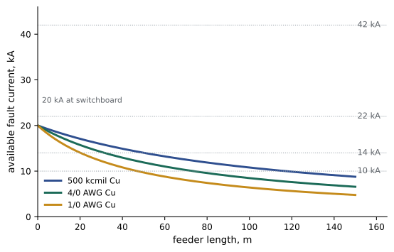
Conductor impedance reduces fault current along a feeder. The ohmic method treats the source as an impedance and adds the feeder impedance: the source impedance per phase is Z_S = V_L ÷ (√3 × I_SC at the source), the feeder impedance is the conductor's impedance per unit length times the length divided by the number of parallel sets, and the fault current at the end is:
Adding impedances arithmetically (rather than as complex numbers) gives a slightly conservative estimate suitable for field checks. Conductor impedances are taken from tables of resistance and reactance per 1,000 ft or per kilometre for each size, material and raceway type. A widely used alternative is the point-to-point method, which computes a factor f = (√3 × L × I_SC) ÷ (C × n × V), where C is a tabulated constant for the conductor and raceway, n the number of parallel conductors, and multiplies the starting fault current by M = 1 ÷ (1 + f). Both methods give similar results.
Worked problem
Fault current at a downstream panel
A 1,000 kVA, 600 V transformer with 5.75 % impedance feeds a switchboard. From it, a 200 ft (61 m) feeder of two parallel sets of 500 kcmil copper in steel conduit supplies a distribution panel. The conductor impedance is about 0.056 Ω per 1,000 ft. Estimate the fault current at the transformer secondary and at the panel (infinite bus, ignoring motors).
Show solution
- FLA = 1,000,000 ÷ (1.732 × 600) = 962 A; I_SC = 962 × 100 ÷ 5.75 = 16,730 A.
- Source impedance: Z_S = 600 ÷ (1.732 × 16,730) = 0.0207 Ω.
- Feeder impedance: 0.056 × 200 ÷ 1,000 ÷ 2 = 0.0056 Ω.
- At the panel: I_SC = 600 ÷ (1.732 × (0.0207 + 0.0056)) = 600 ÷ 0.0456 = 13,170 A.
Answer: About 16.7 kA at the switchboard and 13.2 kA at the panel. Panel devices rated 14 kA would be marginal; 18 kA or 22 kA ratings would be appropriate. Adding motor contribution would raise both values.
Motor contribution
Running motors add fault current for the first few cycles after a fault, which matters for the interrupting and momentary ratings of devices close to large motor loads. A common estimate for induction motors is four times the full-load current of all motors running at the time of the fault, added at the bus where they connect. For example, 500 A of running motor load adds roughly 2,000 A at its bus. Large motors and synchronous motors may contribute more; motors on variable frequency drives contribute little or nothing, because the drive's rectifier blocks reverse power flow.
Types of fault
The three-phase bolted fault (all three phases connected through zero impedance) usually gives the highest current and is used for equipment ratings. Other fault types include line-to-line faults (about 87 % of the three-phase value), line-to-ground faults (which in solidly grounded systems can approach or occasionally exceed the three-phase value near transformers, and in impedance-grounded systems are deliberately limited, Lesson 9), and arcing faults, whose current is lower than bolted fault current because of the arc's resistance (often 40 % to 90 % of bolted current at low voltage). The lower current of arcing faults is important: a protective device may trip slowly on an arcing fault that it would clear instantly as a bolted fault, which increases arc flash energy (Lesson 6). Minimum fault currents also matter, because a device must detect and clear the smallest fault at the end of its circuit.
Applying the results
Short-circuit results are used to:
- Verify that every device's interrupting rating and every assembly's short-circuit rating equal or exceed the available fault current at its location (Lesson 3).
- Verify that conductors, bus and equipment can withstand the fault until the protective device clears it.
- Provide input to coordination and arc flash studies (Lesson 6).
- Set protective device pickups so that minimum faults are detected.
When a system changes, results change. A utility transformer replaced with a larger or lower-impedance unit, added motor loads, a new generator, or shorter or larger feeders can all increase fault current and make previously adequate equipment underrated. Codes require equipment marking of available fault current at services in many cases, and updated studies when systems change. Electricians who notice changes, such as a new, larger utility transformer, should report them to the owner and engineer.
In Canada, the CEC requires equipment to be suitable for the fault current available at its point of installation, and inspection authorities and utilities provide or require fault current information for large services. Engineering studies are commonly performed to CSA and IEEE methods.
Using short-circuit results in the field
Short-circuit calculations are not just a designer's exercise. Electricians use the results every time they add a panelboard, replace a breaker or connect new equipment. The available fault current marked on the service equipment, and on downstream equipment where required, tells the installer the minimum interrupting rating of any device installed there. If a new breaker or piece of equipment has a lower rating than the available fault current, it cannot be installed at that location without further analysis, even if it fits physically.
Fault current changes over the life of a building. The utility may replace its transformer with a larger or lower-impedance unit, add a parallel supply, or reconfigure its network, increasing the fault current available at the service. On-site generators, large motors and battery systems also add fault current. For this reason, short-circuit studies should be reviewed whenever the system changes significantly, and codes in many places require the available fault current marking to be updated when it changes.
A quick estimate can still be useful in the field. Knowing that a transformer secondary's fault current is roughly its full-load current divided by its per-unit impedance allows an electrician to sense-check a label or drawing. If a 75 kVA transformer is labelled with 65 kA available at its secondary panel, something is wrong, because its own impedance limits the fault current to a small fraction of that. Spotting such errors early prevents costly equipment mismatches.
When in doubt, ask the designer or engineer of record for the short-circuit study results before selecting equipment. Proper documentation of available fault current protects both the installer and the owner, and it is often requested by inspectors.
Software tools now perform most short-circuit studies, modelling every cable, transformer, motor and source in the system. These programs can calculate symmetrical and asymmetrical currents, line-to-ground faults and motor contributions at hundreds of buses at once, and they feed directly into coordination and arc flash studies. Their accuracy depends entirely on the input data, so a hand calculation at a few key points remains a valuable check on the software results.
Common mistakes
MistakeAssuming fault current is low because the building is small.
InsteadCalculate from the transformer size and impedance and the utility data.
MistakeIgnoring motor contribution near large motor loads.
InsteadAdd about four times running motor current at the bus.
MistakeAssuming equipment ratings remain adequate after system changes.
InsteadRecalculate when transformers, sources, motors or feeders change.
MistakeUsing bolted fault current to judge protective device speed on arcing faults.
InsteadConsider reduced arcing current, which may delay tripping.
MistakeUsing nominal transformer impedance without tolerance.
InsteadUse minimum impedance for conservative maximum fault current.
Summary and key terms
- Fault current comes from the utility, generators, motors and, to a limited extent, inverters.
- Asymmetrical current depends on X/R; ratings are in symmetrical RMS amperes at test X/R.
- Infinite-bus transformer fault current is full-load current × 100 ÷ %Z.
- Feeder impedance reduces fault current; the ohmic and point-to-point methods estimate it.
- Induction motors contribute about four times their running current briefly.
- Three-phase bolted faults set ratings; arcing faults have lower current and slower clearing.
- Results verify ratings, feed coordination and arc flash studies, and must be updated after changes.
- Available fault current
- The maximum current that would flow in a fault at a point.
- Bolted fault
- A fault with negligible impedance at the fault point.
- Arcing fault
- A fault through an arc, with lower current than a bolted fault.
- Percent impedance
- Transformer impedance expressed as a percentage of rated voltage.
- Infinite bus
- An assumed source with no impedance.
- X/R ratio
- The ratio of reactance to resistance in a fault path.
- Asymmetrical current
- Fault current including a decaying DC offset.
- Motor contribution
- Fault current fed by running motors.
- Point-to-point method
- A simplified method for fault current along conductors.
- Interrupting rating
- The maximum fault current a device can safely interrupt.
Practice problems
Work each problem on paper first, then reveal the answer to check.
Name four sources of fault current.
Show answer
Utility, generators, motors, inverter-based sources.
What is the infinite-bus fault current of a 500 kVA, 208 V, 4 % transformer?
Show answer
FLA 1,388 A; 1,388 × 100 ÷ 4 = 34,700 A.
Why does an infinite-bus calculation give a conservative result?
Show answer
It ignores the utility source impedance, which would reduce the current.
What is the source impedance for 25 kA at 480 V?
Show answer
480 ÷ (1.732 × 25,000) = 0.0111 Ω.
With that source and a feeder of 0.0089 Ω, what is the fault current at the end?
Show answer
480 ÷ (1.732 × 0.02) = 13,860 A.
Estimate motor contribution from 300 A of running induction motors.
Show answer
About 1,200 A.
Why do motors on VFDs contribute little fault current?
Show answer
The drive's rectifier blocks reverse power flow.
What fraction of three-phase fault current is a line-to-line fault?
Show answer
About 87 %.
Why are arcing faults important for protection?
Show answer
Their lower current may delay tripping, increasing arc energy.
Name three system changes that can increase fault current.
Show answer
Larger or lower-impedance utility transformer, added motors, new generator, shorter or larger feeders.
Lesson quiz · 5 questions
Score 60% or more to complete this lesson.
Create a free account to save your progress, take quizzes and earn a certificate.