
ELEC-320 · Lesson 12 of 12 · 26 min
Testing, commissioning and maintenance of distribution systems
A large distribution system is only as reliable as the quality of its installation and the care it receives over its life. Acceptance testing verifies that equipment was built, delivered and installed correctly before it is energized; commissioning verifies that the whole system works as designed, including protective settings, transfer schemes and monitoring; and maintenance keeps it working for decades. Insurance industry data and failure studies consistently show that loose connections, contamination, moisture and lack of maintenance are leading causes of electrical equipment failures and fires. This final lesson covers the testing standards and documents that guide this work, acceptance tests for switchgear, breakers, transformers and cables, energization procedures, commissioning, maintenance programs including thermography and condition-based maintenance, and a capstone project that brings together the whole course.
Standards and documents
- NETA ATS (Acceptance Testing Specifications) and NETA MTS (Maintenance Testing Specifications) from the InterNational Electrical Testing Association list the inspections and tests for each type of equipment, with acceptable values.
- CSA Z463 (Maintenance of electrical systems) is the Canadian standard for electrical preventive maintenance programs, and CSA Z462 governs the safe work practices used during testing and maintenance.
- Manufacturers' instructions give torque values, test procedures and maintenance intervals for specific equipment, and must be followed to keep warranties and listings valid.
- The project specifications define the testing scope, the testing agency's qualifications, and the documents to be delivered to the owner.
- The coordination and arc flash studies provide the settings to be applied and verified.
Acceptance testing
Acceptance tests are performed after installation and before energization. Typical tests include:
- Visual and mechanical inspection: nameplate data versus drawings, physical damage, anchorage, clearances, cleanliness, alignment of draw-out mechanisms, interlocks, labelling and grounding connections.
- Bolted connection checks: verifying torque with a calibrated torque wrench, or measuring the resistance of bolted bus connections with a low-resistance ohmmeter (micro-ohmmeter); values should be similar across phases and within manufacturer limits.
- Insulation resistance: phase to phase and phase to ground on bus, cables and transformers, typically at 1000 V DC for 600 V equipment, with values compared against NETA tables and between phases.
- Contact resistance of breakers and switches, measured across each pole with a micro-ohmmeter at 100 A DC or more.
- Circuit breaker trip testing: primary current injection, which passes high current through the breaker and its sensors to verify long-time, short-time, instantaneous and ground-fault trip times against the manufacturer's curves; or secondary injection, which tests the electronic trip unit directly.
- Transformer turns ratio, winding resistance and insulation tests (Lesson 7).
- Ground-fault protection performance tests (Lesson 9), and grounding electrode resistance tests where specified (Lesson 8).
- Cable tests appropriate to the voltage class (Lesson 11).
- Protective relay testing by secondary injection, verifying each function and setting, and CT and VT ratio and polarity checks.
Worked problem
Evaluating insulation resistance and contact resistance results
During acceptance testing of a 600 V switchboard, insulation resistance readings at 1000 V DC are: A-ground 5,000 MΩ, B-ground 4,800 MΩ, C-ground 45 MΩ. Breaker contact resistance on a 1600 A breaker reads 32 µΩ, 34 µΩ and 95 µΩ on poles A, B and C. What do these results suggest?
Show solution
- Insulation resistance: all readings exceed typical NETA minimums for 600 V equipment, but C-phase is about 100 times lower than the others, which indicates contamination, moisture or damage on C-phase. Investigate before energizing: inspect, clean, and retest.
- Contact resistance: values should be within about 50 % of each other. Pole C at 95 µΩ is nearly three times the others, suggesting a contact problem, contamination or misalignment.
- Exercise the breaker several times and retest; if the high reading persists, the breaker should be inspected by the manufacturer or replaced.
- Record all results, the corrective actions and the retest values in the test report.
Answer: Both C-phase results are abnormal compared with the other phases. Comparison between phases often reveals problems that absolute limits alone would miss.
Energization
Energizing a new large service or distribution system is a planned event, not a casual one. A typical procedure includes: confirming that all acceptance tests are complete and deficiencies corrected; confirming that protective device settings have been applied and verified; removing temporary grounds, tools and debris and closing all covers; confirming that all downstream breakers are open; coordinating with the utility and the authority having jurisdiction; communicating with all trades and clearing people from electrical rooms; wearing PPE from the arc flash labels; then energizing from the source downstream, one level at a time, checking voltage, phase rotation and metering at each step before closing the next device. Transformers are energized one at a time to limit inrush (Lesson 7). After energization, loads are added progressively while monitoring.
Commissioning
Commissioning goes beyond component testing to verify that systems work together as intended. For distribution systems this includes functional testing of automatic transfer switches and generator systems under load, main-tie-main transfer schemes, load shedding, alarms to the building automation system, power monitoring and metering communications, emergency lighting and fire pump power, and surge protection. Integrated systems testing simulates real events, such as a loss of utility power, and confirms that each system responds correctly in sequence. The commissioning process ends with documentation: as-built drawings, final settings, test reports, operation and maintenance manuals, training records for the owner's staff, and updated single-line diagrams and arc flash labels.
Maintenance programs
An effective electrical maintenance program has several elements: an inventory of equipment with its criticality; up-to-date single-line diagrams and studies; inspection, testing and servicing tasks at intervals based on equipment condition, criticality and environment; procedures for safe work; records of results and trends; and a process for correcting deficiencies. Approaches include:
- Time-based preventive maintenance at fixed intervals, often annually for critical equipment and every three to five years for others.
- Condition-based maintenance, which adjusts intervals according to the equipment's condition, environment and criticality, as described in modern maintenance standards; equipment in clean, dry, lightly loaded conditions may be serviced less often, while equipment in harsh environments needs more frequent attention.
- Predictive techniques that detect developing problems without shutdowns: infrared thermography, ultrasonic and partial discharge detection, oil analysis for transformers, and continuous temperature and power quality monitoring.
Typical maintenance tasks for low-voltage switchgear include cleaning, inspecting for signs of heating, tracking or moisture, checking torque, exercising and lubricating breakers per manufacturer instructions, testing trip units, and verifying protective settings match the current coordination study.
Infrared thermography
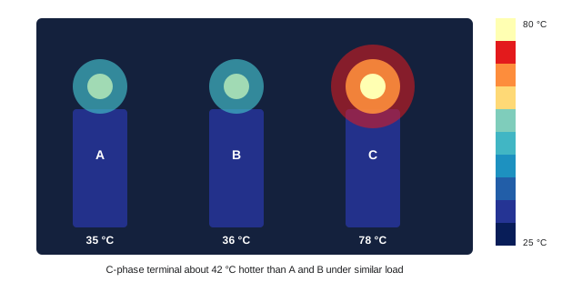
Infrared thermography uses a thermal camera to find abnormally hot connections and components while equipment is energized and loaded, typically at least 40 % of rated load. Inspections are usually done annually, through infrared windows installed in switchgear covers or with covers removed by qualified workers in appropriate PPE. Findings are classified by the temperature rise above a similar component or ambient: for example, a difference of a few degrees may only be monitored, while a rise of 15 °C or more above similar components under similar load indicates a problem needing prompt repair, and much larger differences call for immediate action. Emissivity of the surface, reflections, load and wind (outdoors) affect readings, so thermographers need training and certification. Every repair should be followed by a re-scan to confirm the problem is resolved.
Capstone project
The capstone brings together the course. You will plan the distribution system for a three-storey commercial building with a mix of office, retail and light manufacturing loads, and document your design and installation decisions.
- System and service (Lessons 1 and 2): choose the system voltage and configuration, perform a load calculation, and size the service.
- Equipment (Lessons 3 and 4): select the main switchboard and distribution panelboards, overcurrent devices and their ratings.
- Fault current, coordination and arc flash (Lessons 5 and 6): estimate available fault current at the main and two downstream points, check equipment ratings, sketch a coordination plan, and describe arc flash mitigation.
- Transformers (Lesson 7): size and protect a dry-type transformer serving 120/208 V loads, and describe its grounding as a separately derived system.
- Grounding and ground-fault protection (Lessons 8 and 9): describe the grounding electrode system, size the GEC, main bonding jumper and feeder bonding conductors, and propose GFP settings if required.
- Feeders and power quality (Lesson 10): size a long feeder for voltage drop, address harmonics in the electronic loads, and recommend power factor correction for the manufacturing area.
- Medium voltage (Lesson 11): explain what would change if the building took service at 13.8 kV instead.
- Testing and maintenance (Lesson 12): write an acceptance testing and energization plan and a maintenance program outline.
Worked problem
Starting the capstone load calculation
The building has calculated demand loads of 410 kVA for offices and retail and 290 kVA for manufacturing, served at 347/600 V. Size the main service.
Show solution
- Total demand load: 410 + 290 = 700 kVA.
- Current: 700,000 ÷ (1.732 × 600) = 674 A.
- Select the next standard service rating above the load with growth allowance: an 800 A service gives about 19 % spare capacity.
- At 800 A, ground-fault protection is not required under the 1000 A threshold, but may still be specified.
Answer: An 800 A, 347/600 V service, with the rest of the design following from this choice.
Building a testing and maintenance culture
Testing and maintenance programs succeed when owners, electricians and testing technicians share an understanding of why the work matters. A clear record of each piece of equipment, its test results over time, and the corrective actions taken builds a history that supports good decisions about repair, replacement and capital planning. Software systems for maintenance management can schedule tasks, store test reports and track deficiencies until they are closed.
Electricians often find the first signs of trouble during routine work: a discoloured terminal, a smell of overheated insulation, an unusual hum, or a breaker that feels warm. Reporting these observations promptly and recording them in the maintenance system helps prevent failures. A culture that values these reports, rather than dismissing them as minor, is a strong defence against unplanned outages and fires.
Finally, maintenance programs must keep studies and labels current. Every time equipment is replaced, settings change, or the utility supply changes, the coordination and arc flash studies should be reviewed and labels updated. Keeping single-line diagrams accurate is one of the simplest and most valuable tasks in electrical maintenance, because every future worker depends on them.
Course review: across these twelve lessons you have followed power from the utility supply, through the service and distribution equipment, transformers and feeders, to the testing and maintenance that keep it reliable. The same principles of load, fault current, coordination, grounding and safety appear in every part of the system and every project you will work on.
Common mistakes
MistakeJudging test results only against absolute minimums.
InsteadCompare phases and trends; outliers reveal problems.
MistakeEnergizing before settings are applied and verified.
InsteadApply and test settings from the coordination study first.
MistakeEnergizing all transformers at once.
InsteadEnergize from the source downstream, one level at a time.
MistakePerforming thermography at light load.
InsteadScan at 40 % or more of rated load and re-scan after repairs.
MistakeTreating commissioning as complete without documentation.
InsteadDeliver as-builts, settings, test reports, manuals and training.
Summary and key terms
- NETA ATS and MTS, CSA Z463 and manufacturers' instructions guide testing and maintenance.
- Acceptance testing includes inspection, torque, insulation resistance, contact resistance, trip testing and relay testing.
- Comparing results between phases often reveals defects.
- Energization is planned and proceeds from the source downstream one level at a time.
- Commissioning verifies integrated system operation and delivers complete documentation.
- Maintenance programs combine time-based, condition-based and predictive approaches.
- Thermography under load finds hot connections; re-scan after repairs.
- Acceptance testing
- Testing of equipment after installation and before energization.
- Commissioning
- Verifying that systems work together as designed.
- NETA ATS
- Acceptance testing specifications for electrical equipment.
- Micro-ohmmeter
- An instrument measuring very low resistance.
- Primary injection
- Testing a breaker by passing high current through it.
- Secondary injection
- Testing a trip unit or relay by injecting signals directly.
- Integrated systems testing
- Testing multiple systems together under simulated events.
- Condition-based maintenance
- Maintenance scheduled according to equipment condition.
- Infrared thermography
- Imaging temperatures to find hot spots.
- Infrared window
- A port in an enclosure allowing thermal scanning without opening covers.
Practice problems
Work each problem on paper first, then reveal the answer to check.
What is the difference between acceptance testing and commissioning?
Show answer
Acceptance testing checks individual equipment; commissioning verifies the systems work together.
Name five acceptance tests for switchgear.
Show answer
Visual inspection, torque, insulation resistance, contact resistance, breaker trip testing.
Insulation readings are 4,000, 3,900 and 60 MΩ. What should you do?
Show answer
Investigate the low phase, clean and retest before energizing.
What is primary injection testing?
Show answer
Passing high current through the breaker and sensors to verify trip times.
In what order is a system energized?
Show answer
From the source downstream, one level at a time.
What does integrated systems testing simulate?
Show answer
Real events such as utility power loss.
What is condition-based maintenance?
Show answer
Adjusting intervals based on condition, environment and criticality.
At what minimum load should thermography be performed?
Show answer
About 40 % of rated load.
A connection is 20 °C hotter than similar ones. What action?
Show answer
Plan prompt repair and re-scan afterwards.
What documents complete commissioning?
Show answer
As-builts, settings, test reports, O&M manuals, training records, updated single-lines and labels.
Lesson quiz · 5 questions
Score 60% or more to complete this lesson.
Create a free account to save your progress, take quizzes and earn a certificate.