
ELEC-320 · Lesson 1 of 12 · 26 min
Three-phase systems for services and distribution
Commercial and industrial buildings, data centres, hospitals and factories are supplied by three-phase services carrying hundreds or thousands of amperes. Installing, testing and maintaining these systems is the core work of a Level 3 and 4 electrician and of the industrial and commercial specialist. This course covers the large electrical installation from the utility connection to the branch panels: services and their load calculations, switchboards and switchgear, overcurrent devices, short-circuit calculations, coordination and arc flash, transformers, grounding and bonding, ground-fault protection, feeders and distribution, an introduction to medium voltage, and testing, commissioning and maintenance. This first lesson reviews the three-phase systems used in North American distribution, with the calculations electricians use every day: voltages and connections, power and current, unbalanced loads and neutral current, phase rotation, and the identification of systems in the field.
Why three-phase power
Three-phase power delivers constant total power to a balanced load, unlike single-phase power, which pulses at twice the line frequency. It transmits more power per conductor, produces a rotating magnetic field for motors (ELEC-310), and allows both three-phase and single-phase loads to be served from the same system. A three-phase system has three phase conductors whose voltages are equal in magnitude and displaced by 120°. Two connections are used for transformer windings and loads: wye (star), in which one end of each winding connects to a common neutral point, and delta, in which the windings form a closed triangle.
Common distribution systems
The common low-voltage systems in North American buildings are:
- 120/208 V, 3-phase, 4-wire wye: 208 V line to line, 120 V line to neutral. Used in commercial buildings, apartments and small institutional buildings for lighting, receptacles and small motors.
- 347/600 V, 3-phase, 4-wire wye: 600 V line to line, 347 V line to neutral. The standard system for larger Canadian commercial and industrial buildings: motors and large equipment run at 600 V (575 V utilization), fluorescent and LED lighting at 347 V, and dry-type transformers step down to 120/208 V for receptacles.
- 600 V, 3-phase, 3-wire delta or high-resistance grounded wye: used in industrial plants where continuity of service matters (Lesson 9).
- 120/240 V, 3-phase, 4-wire delta (high-leg or wild-leg delta): an older system in which one transformer winding is centre-tapped to provide 120/240 V single-phase loads, with the third phase (the high leg) at about 208 V to the neutral. The high leg must be identified (orange in the US) and must not be used for 120 V loads.
- 120/240 V, single-phase, 3-wire: residential and small commercial services.
In the wye systems, line-to-line voltage equals √3 times line-to-neutral voltage: 120 × 1.732 = 208 V, 277 × 1.732 = 480 V, 347 × 1.732 = 600 V.
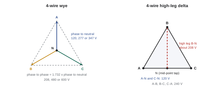
Voltages and currents in wye and delta
In a wye connection, the line current equals the phase (winding) current, and the line voltage is √3 times the phase voltage. In a delta connection, the line voltage equals the phase voltage, and the line current is √3 times the phase current when the load is balanced. These relationships are used when sizing transformer windings, setting overloads on delta-connected motors (ELEC-310), and interpreting measurements.
The total power of a balanced three-phase load is:
where P is real power in watts, S apparent power in volt-amperes, V_L line voltage, I_L line current and PF power factor. Rearranged, the line current for a given kVA is I = kVA × 1,000 ÷ (√3 × V). These formulas are the most frequently used in large installations: transformer full-load current, feeder current, and the capacity of a service all come from them.
Worked problem
Transformer and feeder currents
A 750 kVA transformer supplies a 347/600 V switchboard. What is its full-load secondary current? A 112.5 kVA transformer fed from that switchboard supplies a 120/208 V panel. What are its primary and secondary currents?
Show solution
- 750 kVA at 600 V: I = 750,000 ÷ (1.732 × 600) = 722 A.
- 112.5 kVA primary at 600 V: I = 112,500 ÷ (1.732 × 600) = 108 A.
- 112.5 kVA secondary at 208 V: I = 112,500 ÷ (1.732 × 208) = 312 A.
Answer: About 722 A for the large transformer, and 108 A primary and 312 A secondary for the small one. The ratio of currents is the inverse of the voltage ratio (600 ÷ 208 = 2.9).
Unbalanced loads and neutral current
In a 4-wire wye system, single-phase loads connected from line to neutral are spread across the three phases as evenly as possible, but some unbalance is inevitable. With purely linear loads, the neutral carries the phasor sum of the three phase currents, which is zero when they are balanced and equals the unbalance otherwise. For resistive loads with phase currents I_A, I_B and I_C, the neutral current is:
For example, with 100 A, 80 A and 60 A on the three phases, I_N = √(10,000 + 6,400 + 3,600 − 8,000 − 4,800 − 6,000) = √1,200 = 35 A. Balancing loads across phases therefore reduces neutral current, losses and voltage unbalance.
Non-linear loads, such as computer power supplies, LED drivers and drives, draw currents rich in harmonics. Triplen harmonics (3rd, 9th, 15th) from the three phases are in phase with each other and add in the neutral instead of cancelling, so the neutral of a feeder serving many single-phase electronic loads can carry more current than the phases, up to about 1.7 times phase current in extreme cases (ELEC-210). Codes treat such neutrals as current-carrying conductors for ampacity adjustment, and designers may oversize neutrals or use K-rated transformers (Lesson 10).
Phase rotation and phase identification
Phase rotation (phase sequence) is the order in which the phases reach their peaks: A-B-C or A-C-B. It determines the direction of rotation of three-phase motors, and must be consistent across a facility so that motors, generators, transfer switches and UPS systems connect correctly. Electricians verify phase rotation with a rotation meter before connecting motors, before closing tie breakers and transfer switches, and after utility work. Connecting two sources with opposite rotation, or closing a tie between unsynchronized sources, can cause severe damage.
Conductors are identified by colour so that phases can be traced through a building:
In Canada, the CEC requires the identified (neutral) conductor to be white or grey and bonding conductors green or green with yellow stripe (or bare); phase conductors of three-phase systems, where colour coded, are red, black and blue. The same colours are used on 120/208 V and 347/600 V systems, so equipment must be clearly labelled with the system voltage.
Phase identification also includes labelling of bus bars (A, B, C in a consistent physical order: left to right, top to bottom or front to back as the code specifies) and labelling of panels and switchboards with their source, voltage and available fault current.
Identifying systems in the field
Before working on unfamiliar equipment, determine the system with measurements as well as labels: measure line-to-line and line-to-ground voltages on each phase with a properly rated meter (CAT III or CAT IV). A solidly grounded wye system shows equal line-to-ground voltages at 1/√3 of line voltage. A high-leg delta shows one phase at about 208 V to ground and two at 120 V. An ungrounded delta may show varying or near-zero line-to-ground readings, and a high-resistance grounded system shows roughly normal line-to-ground voltages until a ground fault occurs, when the faulted phase falls toward zero and the others rise toward line voltage (Lesson 9). These readings also detect problems such as a lost neutral, which in a wye system can cause line-to-neutral voltages to swing widely and damage equipment.
Power factor and three-phase power
Real power (kW) does useful work; reactive power (kvar) supports magnetic fields in motors and transformers; apparent power (kVA) is their vector sum and determines the current that conductors and transformers must carry. A plant with a low power factor draws more current for the same real power, requiring larger equipment and often paying utility penalties. Power factor correction capacitors, installed at motors or centrally in switchboards, supply reactive power locally (ELEC-210, Lesson 10).
Worked problem
Service capacity in kW
A 347/600 V service has a 1,600 A main breaker. What is its capacity in kVA, and in kW at a power factor of 0.9?
Show solution
- S = 1.732 × 600 × 1,600 = 1,663 kVA.
- P = 1,663 × 0.9 = 1,497 kW.
- For continuous loading, the code and breaker ratings usually limit continuous load to 80 % of the rating unless the breaker is rated for 100 % continuous operation (Lesson 4).
Answer: About 1,660 kVA, or about 1,500 kW at 0.9 power factor. At 80 % continuous loading the practical continuous capacity is about 1,330 kVA.
Three-phase systems on the job
On a real project, the first question an electrician asks about a new building or an existing plant is what system it has. The answer shapes everything that follows: the voltage rating of every device, the colour coding of the conductors, whether 120 V loads need a step-down transformer, how ground-fault protection must be arranged, and which arc flash category the equipment falls into. Drawings normally state the system on the single-line diagram, but in older buildings the drawings may be missing or wrong, so the system must be confirmed by measurement and by reading nameplates on the service equipment and transformers.
A practical sequence for confirming a system is to read the main nameplate, then measure phase-to-phase and phase-to-ground voltages with a meter rated for the category of the location, and record the results. A wye system shows equal phase-to-ground voltages at line voltage divided by 1.732. A delta system with a grounded centre tap shows one high-leg reading. An ungrounded delta shows unstable or floating phase-to-ground readings, and a corner-grounded delta shows one phase reading zero to ground. Recording these readings on the panel schedule or in a site log saves time for everyone who works on the system later.
Three-phase systems also matter when equipment is moved between buildings or countries. A machine built for one system voltage may not run correctly on another, and motor nameplates, control transformers and drive input ratings must all be checked before connection. Equipment rated for one frequency may overheat or run at the wrong speed on the other. These checks belong to the planning stage, long before the equipment arrives on site.
Common mistakes
MistakeAssuming the neutral carries no current in a wye system.
InsteadCalculate unbalance current and allow for triplen harmonics.
MistakeUsing the high leg of a 4-wire delta for 120 V loads.
InsteadIdentify the high leg and use only the centre-tapped phases for 120 V.
MistakeConnecting motors or sources without checking phase rotation.
InsteadVerify rotation with a meter before energizing or paralleling.
MistakeTrusting labels without measuring.
InsteadMeasure line-to-line and line-to-ground voltages to confirm the system.
MistakeConfusing line and phase current in delta connections.
InsteadApply the √3 relationships correctly for each connection.
Summary and key terms
- Three-phase systems deliver constant power and serve both three-phase and single-phase loads.
- Common Canadian systems are 120/208 V, 347/600 V, 600 V 3-wire and 120/240 V.
- In wye, line voltage is √3 times phase voltage; in delta, line current is √3 times phase current.
- P = √3 V I PF and I = kVA × 1,000 ÷ (√3 V) are the core calculations.
- Neutral current reflects unbalance and triplen harmonics.
- Phase rotation and colour identification must be consistent and verified.
- Field measurements confirm the system type and reveal faults such as lost neutrals.
- Wye (star)
- A connection with windings joined at a common neutral point.
- Delta
- A connection with windings forming a closed triangle.
- Line voltage
- Voltage between two phase conductors.
- Phase voltage
- Voltage across one winding.
- High-leg delta
- A 4-wire delta with one phase at about 208 V to neutral.
- Neutral current
- Current in the neutral from unbalance and harmonics.
- Triplen harmonics
- Odd multiples of the third harmonic that add in the neutral.
- Phase rotation
- The sequence in which phases reach their peaks.
- Apparent power
- The product of voltage and current, in kVA.
- Power factor
- The ratio of real to apparent power.
Practice problems
Work each problem on paper first, then reveal the answer to check.
What is the line-to-neutral voltage of a 600 V wye system?
Show answer
600 ÷ 1.732 = 347 V.
What is the full-load current of a 500 kVA transformer at 208 V?
Show answer
500,000 ÷ (1.732 × 208) = 1,388 A.
What is the line current of a delta load whose phase current is 50 A?
Show answer
50 × 1.732 = 86.6 A.
Phase currents are 120, 120 and 90 A (resistive). What is the neutral current?
Show answer
√(14,400 + 14,400 + 8,100 − 14,400 − 10,800 − 10,800) = √900 = 30 A.
Why can neutrals carry more than phase current?
Show answer
Triplen harmonics from single-phase non-linear loads add in the neutral.
What voltage does the high leg have to neutral in a 120/240 V delta?
Show answer
About 208 V.
When must phase rotation be checked?
Show answer
Before connecting motors, paralleling sources, closing ties and after utility work.
What do equal line-to-ground voltages at 1/√3 of line voltage indicate?
Show answer
A solidly grounded wye system.
What is the kVA capacity of a 1,200 A, 208 V three-phase service?
Show answer
1.732 × 208 × 1,200 = 432 kVA.
Why does low power factor matter?
Show answer
It increases current for the same real power, requiring larger equipment and incurring penalties.
Lesson quiz · 5 questions
Score 60% or more to complete this lesson.
Create a free account to save your progress, take quizzes and earn a certificate.