
ELEC-320 · Lesson 10 of 12 · 26 min
Feeders, busway and power quality in distribution
Between the service and the branch circuits lies the distribution system: the feeders, busways, distribution panelboards and transformers that carry power across a building or plant. Designing and installing feeders involves more than choosing a conductor with enough ampacity. The electrician and designer must consider voltage drop over long runs, harmonic currents that overload neutrals and transformers, power factor and the capacitors used to correct it, the routing and support of large conductors and busway, parallel conductor rules, and metering that lets owners see how energy is used. This lesson covers feeder sizing and routing, parallel conductors, busway, voltage drop calculations, harmonics and neutral sizing, power factor correction, and metering and monitoring.
Feeder sizing
A feeder is sized in several steps. First, determine the calculated load from the load calculation (Lesson 2), applying demand factors and treating continuous loads at 125 % (or selecting conductors and devices so that continuous loads do not exceed 80 % of their rating). Second, select an overcurrent device rated at or above that load. Third, select conductors whose ampacity, after correction for ambient temperature and adjustment for the number of current-carrying conductors in a raceway, is at least the load and is protected by the overcurrent device, observing the temperature rating of the terminations (usually 75 °C for large equipment). Finally, check voltage drop and fault withstand, and size the equipment bonding conductor from the overcurrent device rating (Lesson 8).
In Canada, CEC Section 4 and Tables 1 to 4 give conductor ampacities, with correction factors for ambient temperature (Table 5A) and for more than three conductors in a raceway (Table 5C); Section 8 covers load calculations and the 80 % continuous loading rule for most equipment.
Parallel conductors
Large feeders, from about 400 A upward, are commonly run as sets of parallel conductors, since a single conductor large enough for 1600 A would be impractical to pull and terminate. Paralleling is permitted for conductors 1/0 AWG and larger, provided that each phase, the neutral, and the bonding conductor use conductors of the same length, material, size, insulation type and termination method, so that current divides equally. Each parallel set runs in its own raceway with one conductor of each phase and the neutral in each, so that the magnetic fields cancel and induced heating of steel raceways is avoided. Running all A-phase conductors in one conduit and all B-phase in another causes severe inductive heating of steel conduit and unequal current sharing. Each raceway needs its own full-size bonding conductor where a separate conductor is used.
Busway
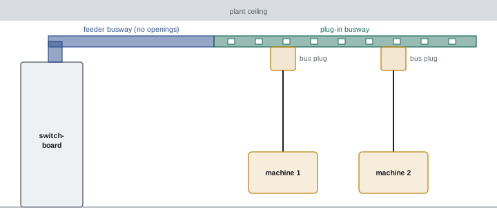
Busway (bus duct) is a prefabricated assembly of copper or aluminum bars in a metal enclosure, available from about 225 A to 6000 A. Feeder busway carries power between switchgear and distribution equipment with low impedance and voltage drop; plug-in busway has openings every 300 mm to 600 mm (1 ft to 2 ft) where bus plugs containing breakers or fusible switches can be inserted to feed loads, making it ideal for manufacturing plants and data centres where loads move. Busway sections bolt together at joints that must be torqued to the manufacturer's values and periodically inspected, since loose joints are a leading cause of busway failure. Installation requirements include support at specified intervals, fire stopping where it passes through rated walls and floors, protection from water (outdoor busway is specifically rated), and expansion joints on long straight runs. Overhead busway in plants allows reconfiguration without new conduit and wire.
Voltage drop
Conductors have resistance (and, for AC, reactance), so current through them causes a voltage drop. Excessive voltage drop makes motors run hot and start slowly, lighting dim, and electronic equipment malfunction. For conductors where reactance is small, voltage drop for three-phase circuits is approximately:
where I is the load current, R is the conductor resistance per unit length, and L is the one-way length. In imperial units with circular mils:
where K is about 12.9 Ω·cmil/ft for copper and 21.2 for aluminum at operating temperature, and L is in feet. For single-phase circuits, replace √3 with 2. For large conductors and long runs, reactance becomes significant, and tables of effective impedance at specified power factor give more accurate results.
In Canada, CEC Rule 8-102 limits voltage drop to 3 % in a feeder or branch circuit and 5 % from the supply side of the consumer's service to the point of utilization, based on the calculated demand load.
Worked problem
Voltage drop on a long feeder
A 400 A, 600 V three-phase feeder uses 500 kcmil copper conductors (resistance about 0.0847 Ω/km at operating temperature) and runs 90 m. Calculate the voltage drop at 400 A.
Show solution
- Vd = 1.732 × 400 × 0.0847 × 0.090 = 5.28 V.
- Percentage: 5.28 ÷ 600 × 100 = 0.88 %.
- This is within the 3 % feeder limit, leaving the remainder of the 5 % total for branch circuits.
- If the run were three times longer, the drop would be about three times greater and could require larger conductors.
Answer: About 5.3 V or 0.9 %, comfortably within the 3 % feeder limit.
Harmonics and neutral sizing
Non-linear loads such as computers, LED drivers, variable frequency drives and UPS systems draw current in pulses, creating harmonic currents at multiples of the fundamental frequency. In a balanced three-phase four-wire system with linear loads, the phase currents cancel in the neutral. Triplen harmonics (3rd, 9th, 15th) from line-to-neutral loads do not cancel; they add in the neutral. In buildings dominated by single-phase electronic loads, neutral current can reach 1.5 to 1.7 times the phase current, overheating a neutral sized equal to the phases. Remedies include:
- Oversized neutrals, often 200 % of phase conductor size, in feeders serving electronic loads, and counting the neutral as a current-carrying conductor for ampacity adjustment.
- K-rated or harmonic mitigating transformers (Lesson 7).
- Harmonic filters (passive tuned filters or active filters that inject cancelling current) near large non-linear loads such as drives.
- Drives with multi-pulse rectifiers or active front ends that draw nearly sinusoidal current.
Harmonics are measured with a power quality analyzer as total harmonic distortion (THD) of current and voltage; IEEE 519 recommends limits at the point of common coupling with the utility. High voltage distortion can cause equipment malfunction, capacitor failure and overheating of motors.
Power factor correction
Inductive loads, especially lightly loaded motors and older lighting, draw reactive power, lowering the power factor. Low power factor increases current for the same real power, which increases losses and voltage drop and uses up capacity in transformers and feeders. Many utilities bill for demand in kVA or apply penalties when power factor falls below about 0.90. Capacitors supply reactive power locally, reducing the current drawn from the utility. The required capacitor rating is:
where P is the real power, and θ1 and θ2 are the angles of the existing and target power factors.
Worked problem
Sizing power factor correction
A plant draws 500 kW at a power factor of 0.80. How many kvar of capacitors are needed to raise the power factor to 0.95?
Show solution
- θ1 = arccos(0.80) = 36.87°, tan θ1 = 0.750.
- θ2 = arccos(0.95) = 18.19°, tan θ2 = 0.329.
- Qc = 500 × (0.750 − 0.329) = 210.5 kvar.
- Apparent power drops from 500 ÷ 0.80 = 625 kVA to 500 ÷ 0.95 = 526 kVA, freeing about 99 kVA of capacity.
Answer: About 210 kvar, typically supplied as an automatic capacitor bank of about 225 kvar in switched steps.
Capacitors may be installed at individual motors (switched with the motor), at motor control centres, or as automatic banks at the service that switch steps in and out to follow the load. Fixed capacitors at the service can overcorrect at light load, raising voltage. In systems with significant harmonics, capacitors can form a resonant circuit with the system inductance near a harmonic frequency, amplifying harmonic currents and voltages and destroying capacitors; detuned banks with series reactors prevent this. Capacitor units must have discharge resistors, and motor-connected capacitors must not exceed the motor's no-load magnetizing kvar, to avoid self-excitation overvoltages when the motor is disconnected.
Metering and monitoring
Utility revenue metering on large services typically uses current transformers and sometimes voltage transformers feeding a meter in a sealed compartment, with the utility specifying the CT cabinet and meter socket. Inside the building, owners increasingly install power meters on main switchgear and major feeders to monitor energy use, demand, power factor, harmonics and events. These meters connect over networks to building automation and energy management systems, support energy codes that require submetering of major end uses, and help with tenant billing, load growth planning and troubleshooting. Installing them requires care with CT polarity and ratio, voltage connections through fused disconnects, and shorting blocks on CT secondaries so that a CT is never open-circuited under load, which would produce dangerous voltages.
Feeders and future growth
Feeders installed today will likely serve loads that change over the building's life. Designers commonly provide spare capacity in feeders and spare conduits between main electrical rooms so that future loads can be added without major construction. Electricians installing feeders can help by labelling both ends clearly, recording routes and lengths on as-built drawings, and noting any spare conduits and pull strings. When feeders are modified later, voltage drop and bonding conductor sizing must be rechecked for the new configuration.
Power quality problems often appear only after a building is occupied and loaded. Flickering lights, overheating neutrals, nuisance tripping and failures of electronic equipment can all be symptoms of harmonics, poor power factor or voltage problems. A power quality survey with a recording analyzer over a week or more captures these issues and guides the right corrective action.
Busway and large feeders also deserve attention during maintenance. Thermal scanning of busway joints and plug-in units, checking torque on accessible connections, and inspecting for moisture or contamination help prevent failures. A busway failure can take an entire floor or production line out of service, so periodic inspection is well worth the effort.
Common mistakes
MistakeGrouping all conductors of one phase in a single steel conduit.
InsteadRun one conductor of each phase and the neutral in each raceway.
MistakeIgnoring voltage drop on long feeders.
InsteadCalculate it and upsize conductors to stay within 3 % and 5 %.
MistakeUsing a standard neutral for feeders serving mostly electronic loads.
InsteadUse an oversized neutral and count it as current-carrying.
MistakeInstalling fixed capacitors on a system with heavy harmonics.
InsteadUse detuned banks or filters after a harmonic study.
MistakeOpening a CT secondary while the primary carries current.
InsteadShort the secondary first using the shorting block.
Summary and key terms
- Feeders are sized from the calculated load, continuous load rules, ampacity corrections and termination ratings.
- Parallel conductors must be identical, with all phases and neutral in each raceway.
- Busway provides compact, low-impedance feeders and flexible plug-in distribution; joints need torque and inspection.
- Voltage drop is limited by CEC 8-102 to 3 % per feeder or branch and 5 % overall.
- Triplen harmonics add in the neutral; oversized neutrals, K-rated transformers and filters address them.
- Capacitors correct power factor; size them with Qc = P(tan θ1 − tan θ2) and beware harmonic resonance.
- Power meters monitor energy and quality; CT secondaries must never be opened under load.
- Feeder
- A circuit between the service and branch circuit overcurrent devices.
- Parallel conductors
- Two or more conductors connected at both ends to share current.
- Busway
- A prefabricated assembly of busbars in an enclosure.
- Bus plug
- A device that plugs into busway to feed a load.
- Voltage drop
- The voltage lost across conductor impedance.
- Triplen harmonics
- Harmonics at multiples of three times the fundamental.
- Total harmonic distortion
- The ratio of harmonic content to the fundamental.
- Power factor correction
- Adding capacitors to supply reactive power locally.
- Detuned capacitor bank
- A capacitor bank with series reactors to avoid resonance.
- Current transformer
- A transformer that produces a small current proportional to line current.
Practice problems
Work each problem on paper first, then reveal the answer to check.
List the steps in sizing a feeder.
Show answer
Calculate load, select the overcurrent device, select conductors with corrected ampacity, check voltage drop and bonding conductor size.
What is the minimum conductor size for paralleling?
Show answer
1/0 AWG.
Why must each raceway contain all phases of a parallel set?
Show answer
To cancel magnetic fields and avoid inductive heating and unequal sharing.
What is the main maintenance concern with busway?
Show answer
Loose joints; check torque and thermography.
Calculate voltage drop: 200 A, 3-phase, 0.2 Ω/km, 100 m.
Show answer
1.732 × 200 × 0.2 × 0.1 = 6.9 V.
What are the usual voltage drop limits?
Show answer
3 % in a feeder or branch and 5 % overall.
Why do neutrals overheat in buildings with electronic loads?
Show answer
Triplen harmonics add in the neutral.
A 300 kW load at 0.75 PF is corrected to 0.95. How many kvar?
Show answer
300 × (0.882 − 0.329) ≈ 166 kvar.
What danger arises with capacitors in a harmonic-rich system?
Show answer
Resonance amplifying harmonics, damaging capacitors.
Why must CT secondaries never be opened under load?
Show answer
Very high voltages develop across the open secondary.
Lesson quiz · 5 questions
Score 60% or more to complete this lesson.
Create a free account to save your progress, take quizzes and earn a certificate.