
ELEC-320 · Lesson 11 of 12 · 23 min
Medium-voltage systems for large facilities
Large facilities such as hospitals, universities, plants, mines and data centres often take service from the utility at medium voltage, typically 4.16 kV to 34.5 kV, and own their own medium-voltage distribution: switchgear, cables, and transformers that step down to utilization voltage at several locations around the site. Taking service at medium voltage reduces the cost per kilowatt-hour, allows power to be distributed efficiently over long distances, and gives the owner control over reliability. It also brings different equipment, different installation methods and much higher hazards. Medium-voltage work requires specific training and qualification; this lesson introduces the systems and practices so that electricians understand what they are working near and what further training they will need. It covers medium-voltage distribution arrangements, switchgear and switches, shielded cables, terminations and splices, cable testing, protective relaying, and safety requirements.
Distribution arrangements
- Radial: a single medium-voltage feeder supplies each transformer. Simple and inexpensive, but a feeder fault or maintenance outage interrupts all downstream loads.
- Loop (open loop): feeders form a ring with a normally open point; each transformer is fed from loop switches that can isolate a faulted cable section and restore power from the other direction. Common on campuses.
- Primary selective: each transformer can be switched between two feeders.
- Secondary selective: two transformers feed a double-ended low-voltage switchgear lineup with a tie breaker; if one transformer or feeder fails, the tie closes and the other transformer carries the critical load. Common in hospitals and data centres.
- Main-tie-main at medium voltage: two utility services feed a medium-voltage switchgear lineup with a tie, with automatic transfer schemes.
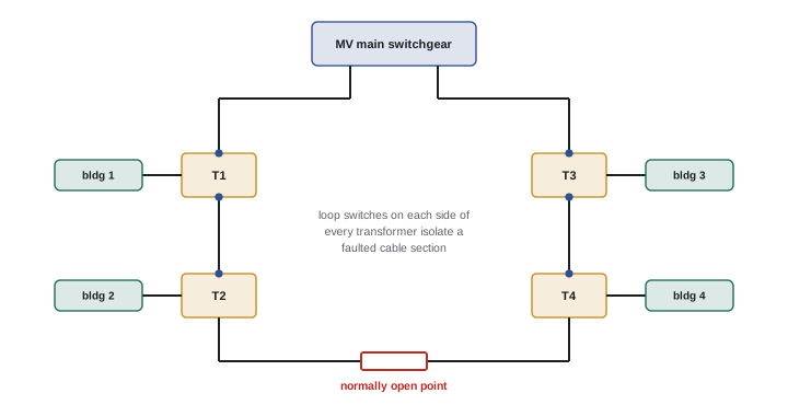
Medium-voltage switchgear and switches
Metal-clad switchgear houses vacuum or SF6 circuit breakers on draw-out trucks, with protective relays, instrument transformers, and grounded metal barriers separating the breaker, bus, cable and instrument compartments. Metal-enclosed switchgear uses load interrupter switches with fuses for transformer protection, and is less expensive. Pad-mounted switches with vacuum or SF6 interrupters are used outdoors on loops. Air-insulated switchgear is common indoors; gas-insulated switchgear is compact and used where space is tight. Arc-resistant switchgear, built and tested to direct the arc products away from the operator through vents or plenums, is increasingly specified. Operating medium-voltage breakers typically involves racking breakers in and out, which is a known arc flash hazard; remote racking devices allow the operator to stand outside the arc flash boundary.
Shielded cables
Medium-voltage cables differ fundamentally from low-voltage cables because of the intense electric field around the conductor. A typical shielded cable consists of:
- A copper or aluminum conductor, usually stranded.
- A semiconducting conductor shield, extruded over the conductor to smooth its surface and eliminate voids where the field would concentrate.
- Insulation of cross-linked polyethylene (XLPE) or ethylene propylene rubber (EPR), rated by voltage class and insulation level (100 %, 133 % or 173 %, depending on how long a ground fault may persist on the system).
- A semiconducting insulation shield bonded to the insulation.
- A metallic shield of copper tape or concentric wires, grounded, which confines the electric field within the cable, carries charging and fault current, and makes the cable safe to touch on the outside when properly grounded.
- An overall jacket.
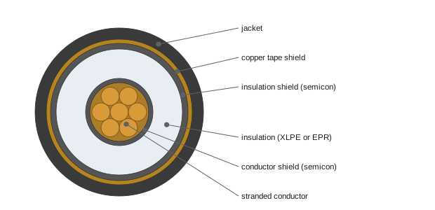
Because the shield confines the field, the voltage stress is uniform and radial inside the insulation. Where the shield is cut back at a termination or splice, the field lines concentrate at the end of the shield, creating very high stress that will break down air and insulation unless controlled. This is why medium-voltage cables require stress-relief terminations and carefully made splices.
Terminations and splices
A termination connects a shielded cable to equipment. It controls the electrical stress at the shield cutback using a stress cone or a high-permittivity stress control tube, provides an external leakage distance (creepage) along the insulation surface with skirts or sheds for outdoor use, and seals out moisture. Terminations may be heat-shrink, cold-shrink or pre-moulded elbow connectors (separable connectors) used on pad-mounted equipment, which can be operated with a hot stick on loadbreak designs. Splices join two cables, rebuilding each layer: conductor connector, conductor shield, insulation, insulation shield, metallic shield continuity and jacket.
The quality of the cable preparation determines whether a termination or splice lasts for decades or fails within months. Typical requirements include: cutting back the jacket, shield and semiconducting layer to exact dimensions from the kit instructions; removing the semiconducting insulation shield cleanly without nicking the insulation; smoothing and cleaning the insulation surface with approved solvents and abrasives; avoiding contamination from hands and dust; and installing compression connectors with the specified die. Many manufacturers and owners require splicers to hold specific training certificates for each product family.
Cable testing
New medium-voltage cables are tested after installation and before energization, and existing cables may be tested during maintenance or after repairs. Common tests include:
- Insulation resistance with a 5 kV or 10 kV insulation tester, a basic check for gross defects, moisture or damage.
- Very low frequency (VLF) withstand testing at 0.1 Hz, applying about two to three times the normal voltage to ground for 15 to 60 minutes; it stresses the insulation without the damage that DC hipot testing can cause in aged XLPE cables.
- Tan delta (dissipation factor) testing, often combined with VLF, measuring dielectric losses to assess insulation aging.
- Partial discharge testing, detecting small discharges in voids or defects in terminations, splices or cable, often online or at power frequency.
- DC hipot testing, historically common, is now generally avoided on service-aged XLPE cable because it can create space charges that accelerate failure after the cable is returned to service, though it is still used on some new cables and other insulation types.
Test voltages and durations follow standards such as IEEE 400 series and the manufacturer's recommendations, along with the specifications of NETA acceptance testing. During testing, the cable ends are hazardous: the far end must be guarded, and after testing the cable must be discharged and grounded, since cables can hold a dangerous charge.
Protective relaying
Medium-voltage breakers are tripped by protective relays fed from current and voltage transformers, rather than by built-in trip units. Modern microprocessor relays combine many functions, identified by IEEE device numbers: 50 (instantaneous overcurrent), 51 (time overcurrent), 50N/51N or 50G/51G (ground overcurrent), 27 and 59 (under- and overvoltage), 81 (frequency), 87 (differential), and 86 (lockout relay). Differential protection compares currents entering and leaving a transformer or bus and trips instantly for internal faults. Relays require a reliable DC control power source, typically a station battery, so that they can trip breakers even during a total loss of AC. Relay settings come from the coordination study and are tested by secondary injection during commissioning.
| Device number | Function | Typical use |
|---|---|---|
| 50 | Instantaneous overcurrent | Fast tripping for high-current faults |
| 51 | Time overcurrent | Inverse-time protection coordinated with downstream devices |
| 50G / 51G | Ground overcurrent | Ground-fault protection |
| 27 / 59 | Undervoltage / overvoltage | Transfer schemes, motor and generator protection |
| 87 | Differential | Transformer, bus and generator protection |
| 86 | Lockout relay | Prevents reclosing until reset after a fault |
Safety on medium-voltage systems
The hazards of medium voltage include shock at higher voltages with larger approach distances, arc flash energies that may be very high because of longer clearing times of upstream utility protection, and induced and stored voltages on de-energized cables. Key practices include:
- Only qualified workers with medium-voltage training work on or near these systems, observing limited and restricted approach boundaries.
- Switching follows written switching orders, often with a second person verifying each step.
- After isolation and lockout, the absence of voltage is verified with a voltage detector rated for the system voltage, tested on a known source before and after use.
- Temporary protective grounds, sized for the available fault current, are applied to all phases at the work location to protect workers if the circuit is accidentally re-energized or picks up induced voltage.
- Arc-rated PPE is selected from the arc flash label, and remote racking and remote operation are used where available.
In Canada, CSA Z462 governs workplace electrical safety, and provincial occupational health and safety regulations set requirements for high-voltage work, including qualification and permit systems; CEC Section 36 covers installations over 750 V.
Working around medium-voltage equipment
Electricians who do not perform medium-voltage work still work near it: in electrical rooms with medium-voltage switchgear, around pad-mounted transformers, and alongside medium-voltage cables in trays and duct banks. Recognizing medium-voltage equipment by its labels, nameplates, larger clearances, warning signs and cable sizes is the first step in staying safe. Medium-voltage equipment rooms are often locked and restricted to qualified persons, and entering them may require a permit or escort.
Medium-voltage cables in cable trays and duct banks must be treated as energized unless they have been isolated, locked out, tested and grounded. Damaged jackets or shields can create hazardous conditions on the cable surface. Excavating near buried medium-voltage cables requires locating services first and hand digging close to marked lines, because striking an energized cable can cause serious injury and widespread outages.
Training for medium-voltage work typically includes theory of medium-voltage systems, switching procedures, use of hot sticks and voltage detectors, temporary grounding, cable splicing and termination, and arc flash hazards specific to medium voltage. Many employers require specific training for each manufacturer's equipment and for splicing kits. Apprentices and journeypersons interested in this field can pursue additional certifications offered by industry associations and manufacturers.
Communication is vital during medium-voltage switching. The person performing the switching, the person verifying, and the control centre or facility manager must all agree on the switching order before it begins. Each step is confirmed aloud and checked off. Interrupting a switching sequence to answer an unrelated question or to rush a step has been a factor in many incidents. Slowing down and following the written order protects everyone on the job.
Protective relays and medium-voltage breakers require periodic maintenance as well. Relays are tested by secondary injection to confirm that their settings and outputs still work, and breakers are exercised, inspected, and tested for contact resistance, insulation resistance and timing. Vacuum interrupters are checked for vacuum integrity with a high-voltage test, and SF6 equipment is checked for gas pressure and leaks. Station batteries supplying trip power need regular inspection and testing, since a failed battery can leave every breaker unable to trip.
Medium-voltage systems are also increasingly monitored online. Continuous partial discharge sensors on switchgear and cable terminations, temperature sensors on bus joints, and relay event records give early warning of developing problems. These data allow owners to plan repairs during scheduled shutdowns rather than responding to failures, which is particularly valuable for facilities that operate around the clock.
Common mistakes
MistakeTreating medium-voltage cables like low-voltage conductors.
InsteadShielded cables need stress-controlled terminations and grounded shields.
MistakeNicking the insulation while removing the semiconducting shield.
InsteadUse the proper tools and follow kit dimensions exactly.
MistakeDC hipot testing aged XLPE cables.
InsteadUse VLF and tan delta methods per IEEE 400.
MistakeLeaving a tested cable ungrounded.
InsteadDischarge and ground it after testing.
MistakeWorking on de-energized MV equipment without temporary grounds.
InsteadVerify absence of voltage and apply protective grounds on all phases.
Summary and key terms
- Large facilities take medium-voltage service and distribute it by radial, loop, primary selective or secondary selective systems.
- Metal-clad switchgear uses draw-out breakers and relays; remote racking reduces arc flash exposure.
- Shielded cables have semiconducting layers and a grounded metallic shield that confines the electric field.
- Terminations control stress at the shield cutback; splices rebuild every layer, and preparation quality is critical.
- VLF withstand, tan delta and partial discharge tests assess cables; DC hipot is avoided on aged XLPE.
- Protective relays with IEEE device numbers trip MV breakers from CTs and VTs, powered by station batteries.
- Qualified workers, switching orders, voltage verification and temporary grounds protect MV work under CSA Z462 and CEC Section 36.
- Medium voltage
- Voltages typically from about 1 kV to 35 kV in distribution.
- Loop system
- A ring feeder with a normally open point.
- Secondary selective
- Two transformers with a low-voltage tie breaker.
- Metal-clad switchgear
- Switchgear with draw-out breakers in compartments with metal barriers.
- Shielded cable
- A cable with semiconducting and metallic shields around the insulation.
- Stress cone
- A device controlling electric stress at a shield cutback.
- Separable connector
- A pre-moulded elbow termination for pad-mounted equipment.
- VLF testing
- Very low frequency withstand testing of cable insulation.
- Protective relay
- A device that detects faults and trips breakers.
- Temporary protective ground
- A grounding set applied to de-energized conductors for worker protection.
Practice problems
Work each problem on paper first, then reveal the answer to check.
Why do large facilities take service at medium voltage?
Show answer
Lower energy rates, efficient distribution over distance, and control of reliability.
What is the advantage of a loop system?
Show answer
A faulted section can be isolated and power restored from the other direction.
What does a secondary selective system provide?
Show answer
A tie breaker allows one transformer to carry critical load if the other fails.
Why is remote racking used?
Show answer
To keep the operator outside the arc flash boundary while racking breakers.
List the layers of a shielded cable.
Show answer
Conductor, conductor shield, insulation, insulation shield, metallic shield, jacket.
Why must the metallic shield be grounded?
Show answer
It confines the field, carries charging and fault current, and keeps the outside safe.
What does a stress cone do?
Show answer
Controls the concentrated electric stress at the shield cutback.
Why is VLF testing preferred over DC hipot for aged XLPE?
Show answer
DC can create space charges that accelerate failure.
What does device number 87 indicate?
Show answer
Differential protection.
Why are temporary protective grounds applied?
Show answer
To protect workers from accidental re-energization or induced voltage.
Lesson quiz · 5 questions
Score 60% or more to complete this lesson.
Create a free account to save your progress, take quizzes and earn a certificate.