
ELEC-220 · Lesson 9 of 12 · 31 min
Emergency and standby systems
When normal power fails, some loads must keep running to protect life: exit signs and egress lighting so people can leave safely, fire alarm systems, fire pumps, smoke control fans and elevators for firefighters. Others must keep running to protect property, processes or business: refrigeration, data centres, industrial processes and communications. The code distinguishes these categories and sets stricter rules for the life-safety systems, covering how quickly power must be restored, how wiring is separated, how circuits are protected and how systems are tested. This lesson covers the categories of systems, sources of emergency power, transfer equipment, wiring and selective coordination, sizing generators and batteries, and testing and maintenance.
Categories of systems
In Canada, the National Building Code (Subsection 3.2.7) determines which buildings need emergency lighting and emergency power, and for how long, and CSA C282 (Emergency electrical power supply for buildings) sets requirements for generator systems that supply emergency loads. Section 46 of the CEC covers the installation of emergency systems, unit equipment and exit signs, and Section 32 the fire alarm systems and fire pumps they supply. Loads that are not required by the building code (for example data centre loads or process equipment) are optional standby loads, wired under the general rules and often supplied by the same generator through separate transfer switches.
| Category | Purpose | Typical requirement |
|---|---|---|
| Emergency (life safety) | Egress lighting, exit signs, fire alarm, fire pumps, elevators for firefighters | Emergency lighting immediately (batteries) and generator power within 10 s (CSA C282) |
| Other required loads | Smoke control, ventilation, sewage pumps, communications | As specified by the building code and CSA C282 |
| Optional standby | Data centres, refrigeration, industrial processes, business continuity | Owner's choice |
Sources of emergency power
Emergency power can come from several sources, alone or combined:
- Generator sets (diesel, natural gas or propane), sized for the connected emergency loads, starting automatically on loss of normal power. Diesel sets are the usual choice for emergency service because they start quickly and store their own fuel; natural gas units depend on the gas utility, which some codes accept only with conditions.
- Storage batteries: central battery systems or unit equipment (self-contained battery packs with lamps or remote heads) that provide immediate lighting for a rated time.
- Uninterruptible power supplies (UPS) for loads that cannot tolerate even a brief interruption, such as fire alarm control panels (which have their own batteries) and data processing equipment.
- A separate service from the utility, in some cases, where permitted by the authority.
CSA C282 requires emergency generators to be capable of supplying the emergency load within 10 seconds of a power failure, to have enough fuel for at least 2 hours of operation at full load (more where the building code requires a longer duration), and to have automatic starting, specified alarms and annunciation.
Emergency lighting
Emergency lighting must illuminate exits, corridors, stairs and paths of egress so occupants can find their way out when normal lighting fails.
The NBC requires emergency lighting to provide an average illuminance of not less than 10 lx at floor or tread level along means of egress, with a minimum duration that depends on the building (30 minutes for most buildings, longer for high buildings and certain occupancies). Exit signs must be continuously illuminated and supplied by emergency power. Unit equipment is certified to CSA C22.2 No. 141.
Worked problem
Battery unit capacity
A unit equipment battery supplies four 6 W LED remote heads plus a 2 W internal load at 12 V DC. What battery capacity is needed for 90 minutes (for a 30-minute requirement, scale accordingly), allowing for a 20% end-of-life capacity margin?
Show solution
- Load: \(4 \times 6 + 2 = 26\) W; current \(= 26/12 = 2.17\) A.
- 90 min: \(2.17 \times 1.5 = 3.25\) Ah; with margin \(3.25/0.8 = 4.1\) Ah.
- 30 min: \(2.17 \times 0.5/0.8 = 1.4\) Ah.
Answer: About 4.1 Ah for 90 minutes, or 1.4 Ah for 30 minutes. Manufacturers rate unit equipment by the wattage it can supply for the required duration, and the remote heads' wiring must be sized so voltage drop at 12 V does not dim them excessively.
Transfer switches
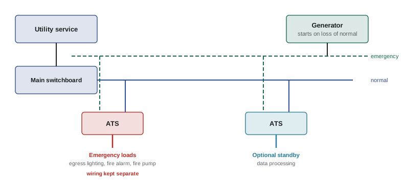
Automatic transfer switches (ATS) monitor normal power and, when it fails, signal the generator to start and transfer the load once the generator's voltage and frequency are acceptable. When normal power returns and stabilizes, they transfer back after a time delay and let the generator run unloaded to cool down. Transfer switches are designed and tested to withstand the available fault current and to switch motor and transformer loads (DCE-340 covers open, closed and delayed transition types). Emergency loads are supplied through transfer switches that serve only emergency loads, so that faults or overloads in other loads cannot compromise them. Large generators may also use load shedding: if the generator becomes overloaded, lower-priority loads are dropped to protect the emergency loads.
Transfer switches for emergency systems are certified to CSA C22.2 No. 178.1 and installed under Section 46 and CSA C282, with the emergency loads on their own transfer equipment.
Wiring and separation
Emergency wiring must survive the events that cause the emergency and must not be affected by failures of other systems:
- Separation: emergency circuits run in their own raceways, cables, boxes and enclosures, not mixed with normal or optional standby wiring, except in transfer switches, exit and emergency luminaires supplied from two sources, and specified common junction boxes.
- Identification: emergency panels, boxes and receptacles are marked (often red) so they are recognized.
- Fire resistance: in high-rise and large assembly buildings, feeders for emergency systems may need fire-rated cable or protection by fire-rated construction for a specified time (typically 1 or 2 hours), so a fire does not disable fire pumps, elevators and smoke control.
Section 46 and Section 32 of the CEC, together with NBC Article 3.2.7.10 and related requirements, require emergency conductors to be separated from other wiring and, for certain systems in buildings such as high buildings, to be protected against fire for specified durations, for example by installation in a fire-rated enclosure, by burial in concrete, or by use of cables certified for circuit integrity.
Selective coordination
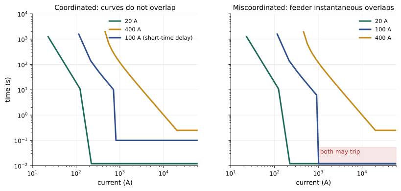
If a fault occurs on one emergency branch circuit, only the overcurrent device nearest the fault should open, leaving all other emergency loads energized. If an upstream feeder breaker opened instead, an entire floor's egress lighting or the whole emergency system could go dark during an emergency. Selective coordination means choosing overcurrent devices so that, for every possible fault current, the downstream device opens before any upstream device. It is checked with time-current curves and manufacturers' coordination tables, and often requires fuses with suitable ratios or breakers with adjustable short-time settings and no instantaneous trip upstream.
The CEC requires overcurrent devices in emergency systems to be coordinated in accordance with the Code's rules for these systems, and designers commonly apply full selective coordination for emergency and fire pump circuits as good practice.
Worked problem
Coordination with fuse ratios
A manufacturer's table states that its time-delay fuses coordinate when the upstream fuse rating is at least 2 times the downstream rating. An emergency panel has 20 A, 30 A and 60 A branch fuses, fed by a 100 A feeder fuse from a 225 A main fuse. Are they selectively coordinated?
Show solution
- Largest branch 60 A to feeder 100 A: ratio 1.67, less than 2.
- Feeder 100 A to main 225 A: ratio 2.25, adequate.
Answer: Not fully: a fault on the 60 A branch could open the 100 A feeder fuse as well. Raising the feeder fuse to 125 A (ratio 2.08) or reducing the largest branch to 50 A (ratio 2.0) achieves coordination, provided conductors and loads still suit. Breakers are checked similarly with time-current curves and published tables, which typically show instantaneous trips limit coordination at high fault currents.
Sizing generators
Generators must supply the running load and also handle the inrush of large motors starting. When a large motor starts on a generator, its starting current (several times running current, at low power factor) causes a voltage dip and frequency drop that can drop out contactors, extinguish discharge lamps or trip drives. Sizing therefore considers:
- The total running load in kW and kVA, with future growth.
- Step loads: the largest block applied at once, often limited by sequencing transfer switches or motor starts.
- Motor starting kVA and the acceptable voltage dip (often 15 to 20% for emergency loads); reduced-voltage starters and drives reduce starting kVA.
- Nonlinear loads (UPS, drives), which can cause voltage distortion and may require oversizing.
Generator manufacturers provide sizing software and data on transient response for these checks.
Worked problem
Motor starting on a generator
A 500 kW (625 kVA) generator has a subtransient reactance that gives a voltage dip of about 1% per 7 kVA of motor starting load applied, as a rough guide. A 50 hp fire pump starts across the line with locked-rotor kVA of 6 kVA/hp (code letter range G). Estimate the dip, and compare with a soft starter limiting starting kVA to 3 kVA/hp.
Show solution
- Across the line: \(50 \times 6 = 300\) kVA; dip \(\approx 300/7 = 43\%\).
- Soft start: \(50 \times 3 = 150\) kVA; dip \(\approx 21\%\).
Answer: Across-the-line starting would collapse the voltage by about 40%, enough to drop out other emergency loads; a soft starter halves the dip. In practice, a larger generator, sequential starting of loads, or a reduced-voltage starter (permitted for fire pumps when listed) is selected using the manufacturer's detailed data. Fire pump rules require the generator to start and run the pump without the voltage at the controller falling more than 15%.
Worked problem
Fuel for required run time
A 400 kW diesel generator consumes about 110 L/h at full load. What fuel storage is needed for the CSA C282 minimum of 2 hours at full load, and for 24 hours for a facility that wants extended resilience?
Show solution
- 2 h: \(2 \times 110 = 220\) L; 24 h: 2640 L.
Answer: At least 220 L for the code minimum, or about 2700 L for 24 hours, plus an allowance for unusable fuel at the tank bottom. Larger tanks bring fuel storage requirements under the fire code and environmental rules (DCE-340).
Testing and maintenance
Emergency systems must work on the rare day they are needed, so codes require regular testing and records:
CSA C282 requires weekly inspection and monthly operation of emergency generators under load, with annual testing and maintenance and written records. Unit equipment is tested monthly for a short period and annually for its rated duration under CSA C22.2 No. 141 and the fire code. The provincial fire code assigns responsibility for testing to the building owner.
Diesel engines run lightly loaded for long periods suffer wet stacking (unburned fuel accumulating in the exhaust), which is why minimum test loads or periodic load bank tests are required. Fuel quality must also be maintained, since diesel degrades and accumulates water and microbial growth over months.
Lesson 10 covers fire alarm systems, which share many interfaces with emergency power, and Lesson 12 the testing and documentation that close out a project.
Common mistakes
MistakeMixing emergency and normal wiring in the same raceways or boxes.
InsteadKeep emergency wiring separate except where the code permits.
MistakePutting emergency and optional loads on one transfer switch.
InsteadUse separate transfer switches so other loads cannot compromise emergency loads.
MistakeIgnoring selective coordination in emergency systems.
InsteadVerify coordination for all fault currents with curves and manufacturer tables.
MistakeSizing a generator for running load only.
InsteadCheck motor starting, step loads, voltage dip and nonlinear loads.
MistakeRunning only no-load generator tests.
InsteadTest under adequate load to prove capacity and prevent wet stacking.
Summary and key terms
- The NBC and CSA C282 set where emergency power is needed and how it is supplied; CEC Section 46 covers installation.
- Emergency generators must supply load within 10 s with at least 2 hours of fuel.
- Sources include generators, batteries, UPS and in some cases separate services.
- Emergency lighting provides at least 10 lx average along egress paths for the required duration.
- Emergency loads use dedicated transfer switches; load shedding protects them on overload.
- Emergency wiring is separated, identified and fire-protected where required.
- Selective coordination ensures only the device nearest a fault opens.
- Generators are sized for motor starting and step loads, and tested regularly under load.
- Emergency system
- A system required by code to supply life-safety loads when normal power fails.
- CSA C282
- The standard for emergency electrical power supply for buildings.
- Unit equipment
- A self-contained battery emergency lighting unit.
- Automatic transfer switch
- A switch that transfers load to an alternate source on loss of normal power.
- Load shedding
- Disconnecting lower-priority loads to protect higher-priority ones.
- Selective coordination
- Arrangement where only the overcurrent device nearest a fault opens.
- Circuit integrity cable
- Cable certified to keep operating during a fire for a specified time.
- Step load
- A block of load applied to a generator at one time.
- Voltage dip
- The temporary voltage drop when a large load is applied.
- Wet stacking
- Unburned fuel accumulating in a lightly loaded diesel engine's exhaust.
Practice problems
Work each problem on paper first, then reveal the answer to check.
Who determines which buildings need emergency power in Canada?
Show answer
The building code (NBC Subsection 3.2.7 and provincial codes), with CSA C282 for generator systems.
Maximum time to restore emergency power?
Show answer
10 seconds.
Unit equipment load 36 W at 6 V for 90 minutes with 20% margin. Battery capacity?
Show answer
6 A × 1.5 h / 0.8 = 11.25 Ah.
Why do emergency loads get their own transfer switch?
Show answer
So faults or overloads on other loads cannot interrupt them, and they can be prioritized.
What is selective coordination and why does it matter in emergency systems?
Show answer
Only the device nearest the fault opens, so a single fault does not black out other emergency loads.
Coordination needs a 2:1 fuse ratio. Branch fuses up to 40 A. Minimum feeder fuse?
Show answer
80 A.
A 30 hp motor at 6 kVA/hp starting on a generator with 1% dip per 5 kVA. Dip?
Show answer
180 kVA → 36%.
Generator uses 80 L/h. Fuel for 2 hours plus 10% unusable?
Show answer
176 L.
What is wet stacking and how is it prevented?
Show answer
Unburned fuel in the exhaust from light loading; test under adequate load or with load banks.
Why might emergency feeders need fire-rated protection?
Show answer
So a fire does not disable fire pumps, smoke control and elevators while they are needed.
Lesson quiz · 5 questions
Score 60% or more to complete this lesson.
Create a free account to save your progress, take quizzes and earn a certificate.