
ELEC-220 · Lesson 8 of 12 · 30 min
Industrial control panels and machinery
Industrial electricians spend much of their time not on building wiring but on machines and the control panels that run them: motor starters and drives, programmable logic controllers (PLCs), sensors, safety relays, operator stations and the wiring between them. Lesson 3 covered motor branch circuits and basic control circuits. This lesson covers the construction and certification of industrial control panels, their short-circuit current ratings, enclosure types and heat management, control power and wiring practice, PLC input and output wiring, machine safety circuits including emergency stops, and the lockout and energy control procedures that protect workers who maintain machinery.
Industrial control panels
An industrial control panel is an assembly of two or more power circuit components (such as disconnects, fuses, breakers, contactors and drives), control circuit components (such as PLCs, relays and pushbuttons), or a combination, with associated wiring and terminals, in an enclosure. Panels are built in shops to a product standard and certified as an assembly, so that the inspector can accept the panel as a unit rather than inspecting every internal connection.
In Canada, industrial control panels are built and certified to CSA C22.2 No. 286, Industrial control panels and assemblies, and industrial machinery to CSA C22.2 No. 301, Industrial electrical machinery. Uncertified panels and machines, including many imported machines, require field evaluation by an accredited certification or evaluation body (to CSA SPE-1000 or provincial requirements) before they can be connected. The CEC applies up to the supply terminals of the machine or panel.
Panel nameplates must show the supply voltage, phase and frequency, the full-load current, the short-circuit current rating, the enclosure type and a wiring diagram number, so that the installer can size the feeder and check the panel against the available fault current.
Short-circuit current rating of panels
A control panel's short-circuit current rating (SCCR) is the fault current it can withstand when protected by the specified overcurrent device (Lesson 4). It is determined by the weakest component in the power circuit, adjusted for current-limiting devices ahead of it. A common method, in UL 508A Supplement SB and the corresponding CSA C22.2 No. 286 annex, works as follows: find the rating of each power circuit component (contactors, overload relays, terminal blocks, drives, power supplies); the panel SCCR is the lowest of these, unless a current-limiting fuse or breaker upstream limits the let-through current below that component's rating, in which case the component may be rated higher in combination; tested combinations (for example a motor starter tested with specified fuses at 65 kA) can be used at their tested rating.
Worked problem
Panel SCCR
A panel has a main fused disconnect with Class J fuses (200 kA interrupting), a power distribution block rated 10 kA, contactors and overloads with a tested combination rating of 65 kA with Class J fuses, and a drive rated 65 kA with specified fuses. The available fault current at the panel is 42 kA. Is the panel adequate?
Show solution
- The power distribution block, at 10 kA, is the weakest component and limits the panel SCCR to 10 kA unless its rating can be increased by the current-limiting fuses ahead of it (some blocks are listed for higher ratings when protected by Class J fuses of a specified size).
- If the block is listed for 100 kA behind Class J fuses, the next weakest are the starters and drive at 65 kA, so the panel SCCR becomes 65 kA.
- Compare: 65 kA exceeds the 42 kA available; 10 kA would not.
Answer: With the block's high-fault rating behind Class J fuses, the panel can be marked 65 kA and is adequate. Without it, the panel is limited to 10 kA and cannot be installed where 42 kA is available. Low SCCR is one of the most common reasons control panels are rejected at inspection.
Enclosures and environmental ratings
Enclosures protect equipment from the environment and people from live parts. Enclosure types are defined in North American standards (CSA C22.2 No. 94 and NEMA 250), and internationally by the IP code (IEC 60529):
| Type | Protection | Typical use | Approximate IP |
|---|---|---|---|
| 1 | indoor, contact with live parts, falling dirt | clean, dry indoor areas | IP20 |
| 3R | outdoor, rain, sleet, snow | outdoor equipment | IP14 |
| 4 | indoor or outdoor, hose-directed water, windblown dust | washdown areas, outdoors | IP66 |
| 4X | as Type 4 plus corrosion resistance | food processing, chemical, marine | IP66 |
| 12 | indoor, dust, dripping non-corrosive liquids | industrial machinery and factories | IP54 |
An enclosure is only as good as its installation: conduit entries must use fittings rated for the enclosure type, unused holes must be sealed, and drilling the top of a Type 4 enclosure without a suitable fitting defeats its rating. In hazardous locations, enclosures and methods from Lesson 5 apply.
Heat in enclosures
Drives, power supplies, contactors and PLCs dissipate heat, and a sealed enclosure can overheat its contents, shortening their life or causing trips. The temperature rise of a sealed enclosure is roughly the heat dissipated divided by the product of the effective surface area and a heat transfer coefficient (about 5.5 W/m²·K for painted steel in still air):
Worked problem
Cooling a drive panel
A painted steel enclosure 1.2 m high, 0.8 m wide and 0.4 m deep, mounted against a wall, contains drives and power supplies dissipating 450 W. The surrounding air reaches 35 °C and the components are rated for 50 °C inside the enclosure. Is natural cooling enough? If not, what fan airflow is needed?
Show solution
- Effective area (front, top and sides; back against the wall excluded): \(1.2 \times 0.8 + 0.8 \times 0.4 + 2 \times 1.2 \times 0.4 = 0.96 + 0.32 + 0.96 = 2.24\) m².
- Rise: \(450/(5.5 \times 2.24) = 36.5\) K, giving 71.5 °C inside, far above 50 °C.
- Fan airflow for a 15 K rise: \(\dot V = P/(\rho c_p \Delta T) = 450/(1.2 \times 1{,}005 \times 15) = 0.025\) m³/s, about 90 m³/h, increased by about 30% for filter loading and altitude.
Answer: Natural cooling is inadequate. A filtered fan of about 120 m³/h, or an enclosure air conditioner or heat exchanger where the air is dirty or the enclosure must stay sealed (for example Type 12 or 4 environments), is needed. Moving drives to through-panel mounting, with heat sinks outside the enclosure, is another common solution.
Control power and wiring practice
Control circuits typically run at 120 V AC from a control power transformer or, increasingly, at 24 V DC from a power supply, which is safer to work near and suits PLCs and sensors. Control transformers must be protected on the primary and secondary as the code requires (Lesson 3), and one side of the control circuit is usually grounded so that a ground fault trips the protective device rather than energizing a coil unexpectedly. Good practice and the machinery standards require:
- Wire colour coding so that circuits can be identified. Under NFPA 79 and common North American machinery practice: black for AC and DC power circuits, red for AC control, blue for DC control, orange (or yellow) for control circuits energized from external sources that remain live when the panel disconnect is off, white or grey for grounded AC conductors, white with blue stripe for grounded DC conductors, and green or green-yellow for protective bonding.
- Wire and terminal identification matching the drawings, on both ends of every wire.
- Separation of power, control and communication wiring, with drive output cables shielded and routed away from signal cables to limit interference.
- Terminals and wire sizes appropriate for the current and the overcurrent protection, with ferrules on fine-stranded wire.
- Spare capacity in wiring ducts, terminals and DIN rail for future changes.
PLC input and output wiring
A PLC reads inputs from pushbuttons, limit switches, proximity sensors and analog transmitters, executes its program, and drives outputs such as contactor coils, solenoid valves, indicator lamps and drive references. Wiring must match the module type:
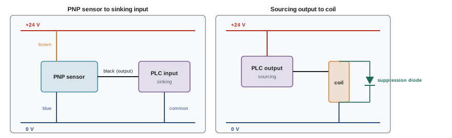
- Sinking and sourcing: on a sourcing (PNP) sensor or output, the device switches the positive supply to the load; on a sinking (NPN) device, it switches the load to the common (0 V). A sourcing sensor must connect to a sinking input module and vice versa. PNP is the norm in North America and Europe, NPN in parts of Asia.
- Analog signals: 4 to 20 mA current loops are preferred over voltage signals for long runs because they are immune to voltage drop and the "live zero" of 4 mA distinguishes a zero reading from a broken wire. Shielded twisted pair cable, with the shield grounded at one end, reduces noise.
- Output protection: inductive loads such as coils and solenoids produce voltage spikes when switched off; suppressors (diodes on DC, RC networks or varistors on AC) protect the outputs.
- Industrial networks (EtherNet/IP, PROFINET, Modbus TCP and others) increasingly replace hard-wired I/O, with remote I/O blocks near the machine, reducing wiring but requiring network design and cybersecurity.
Machine safety circuits
Machines must protect people from moving parts, which requires both guarding and control circuits designed so that failures do not create danger. The machinery standards set requirements for:
- Emergency stops: red mushroom-head actuators on a yellow background, located at each operator station and where needed, which latch when pressed and must be manually reset. A stop category 0 removes power immediately (uncontrolled stop); category 1 brings the machine to a controlled stop and then removes power; category 2 is a controlled stop with power left available, not permitted for emergency stops.
- Safety-related control: safety relays and safety PLCs monitor emergency stops, guard door interlocks, light curtains and two-hand controls with redundant, monitored channels, so that a single fault, such as a welded contactor or a shorted wire, is detected and does not prevent the machine from stopping. The required reliability is expressed as a performance level (PLa to PLe) under ISO 13849-1 or a safety integrity level under IEC 62061, determined from a risk assessment.
- Safe torque off: drives with a certified safe torque off input remove torque without removing power from the drive, giving a fast, reliable stop function.
- Restart prevention: after a stop or power loss, the machine must not restart automatically; a deliberate start command is required.
In Canada, CSA Z432, Safeguarding of machinery, sets requirements for guards, safety devices and safety-related controls, referencing ISO 13849 and IEC 62061, and provincial occupational health and safety regulations require machine guarding and pre-start health and safety reviews in some provinces (for example Ontario's Regulation 851, section 7).
Worked problem
Why redundant monitored contactors?
A press uses a single contactor controlled by the emergency stop to remove motor power. Over years of operation the contactor's main contacts weld closed. What happens when the emergency stop is pressed, and how does a category 3 or 4 design prevent this?
Show solution
- With one contactor, the welded contacts keep the motor running even though the coil is de-energized: the emergency stop fails silently.
- A redundant design uses two contactors in series, each able to stop the motor, so one welded contactor does not prevent stopping.
- Mechanically linked (force-guided) auxiliary contacts on each contactor are monitored by the safety relay, which refuses to allow a restart if either contactor has not opened, revealing the fault.
Answer: A single contactor creates a hidden single point of failure. Redundancy with monitoring detects the first fault and prevents restart until it is repaired, which is the essence of category 3 and 4 architectures required for high-risk machines.
Lockout and hazardous energy control
Before maintenance or repair, machines must be isolated from all energy sources, electrical, pneumatic, hydraulic, mechanical (springs, raised loads, flywheels), thermal and chemical, and the isolation locked and verified. A typical lockout procedure: notify affected workers; shut down the machine normally; isolate every energy source at its disconnecting device; apply personal locks and tags (each worker applies their own lock, often using a group lockout box for large jobs); release or restrain stored energy, such as bleeding pressure and blocking raised parts; verify isolation by attempting to start the machine and testing for absence of voltage with a properly tested meter; and only then begin work. Removing locks follows a reverse procedure, with each worker removing only their own lock.
In Canada, CSA Z460, Control of hazardous energy: lockout and other methods, is the reference standard, and provincial occupational health and safety regulations require lockout before servicing machinery. Disconnecting means for machines must be lockable in the open position.
Common mistakes
MistakeInstalling a control panel without checking its SCCR against available fault current.
InsteadRead the nameplate SCCR and compare it with the marked available fault current.
MistakeMounting drives in a small sealed enclosure without a heat calculation.
InsteadCalculate heat load and provide fans, air conditioning or through-panel mounting.
MistakeWiring a PNP sensor to a sourcing input.
InsteadMatch sourcing devices with sinking inputs and vice versa.
MistakeUsing a single unmonitored contactor for an emergency stop on a hazardous machine.
InsteadUse redundant, monitored safety circuits at the required performance level.
MistakeRelying on a stop button instead of lockout during maintenance.
InsteadIsolate, lock, release stored energy and verify before work.
Summary and key terms
- Industrial control panels are shop-built assemblies certified to CSA C22.2 No. 286 or listed to UL 508A, with nameplate data for installation.
- Panel SCCR is set by the weakest power component, adjusted by current-limiting devices and tested combinations.
- Enclosure types (1, 3R, 4, 4X, 12) define environmental protection; heat loads must be calculated and managed.
- Control circuits use protected control power, colour coding, identification and separation of power and signal wiring.
- PLC wiring matches sinking and sourcing devices, uses 4 to 20 mA loops for analog signals, and suppresses inductive loads.
- Machine safety uses emergency stops, monitored redundant safety circuits, safe torque off and restart prevention.
- Lockout isolates and verifies all hazardous energy before maintenance.
- Industrial control panel
- An assembly of power and control components in an enclosure.
- SCCR
- The fault current a panel can withstand with specified protection.
- Enclosure type
- A rating of protection against environmental conditions.
- Control power transformer
- A transformer supplying control circuits.
- Sourcing device
- A device that switches the positive supply to its load.
- Sinking device
- A device that switches its load to the common.
- 4 to 20 mA loop
- An analog signal standard using current, with a live zero.
- Stop category
- A classification of how a machine is stopped (0, 1 or 2).
- Performance level
- A measure of the reliability of safety-related control functions.
- Lockout
- Isolating and locking energy sources before servicing equipment.
Practice problems
Work each problem on paper first, then reveal the answer to check.
What standard covers industrial control panels in Canada?
Show answer
CSA C22.2 No. 286.
What sets a panel's SCCR?
Show answer
The weakest power circuit component, adjusted for current limiting and tested combinations.
Which enclosure type suits washdown areas?
Show answer
Type 4 or 4X.
Temperature rise for 300 W in a 2.0 m² enclosure at 5.5 W/m²K?
Show answer
27 K.
Fan airflow to remove 600 W with a 10 K rise?
Show answer
\(600/(1.2 \times 1{,}005 \times 10) = 0.05\) m³/s (180 m³/h).
What colour identifies DC control wiring under NFPA 79?
Show answer
Blue.
What input type does a PNP sensor need?
Show answer
A sinking input.
Why is 4 mA used as the zero of an analog loop?
Show answer
To distinguish zero from a broken wire.
Which stop category is not allowed for emergency stops?
Show answer
Category 2.
What is the last step before starting work after lockout?
Show answer
Verify isolation, including testing for absence of voltage.
Lesson quiz · 5 questions
Score 60% or more to complete this lesson.
Create a free account to save your progress, take quizzes and earn a certificate.