
ELEC-220 · Lesson 6 of 12 · 31 min
Grounding and bonding in commercial and industrial systems
Grounding and bonding are among the most misunderstood parts of electrical work, and errors are dangerous: a missing bonding connection can leave metal enclosures energized during a fault, and an extra neutral-to-ground connection can send current through piping and cable shields. ELEC-130 covered grounding and bonding for dwellings. Commercial and industrial systems add larger services, several voltage systems created by transformers, standby generators, impedance-grounded systems that keep running after a ground fault, and large metal structures and piping systems that must be bonded. This lesson explains the purposes of grounding and bonding, the types of system grounding, service and separately derived system connections, sizing and installing bonding conductors, effective fault-current paths, grounding electrodes and testing.
Two different jobs: grounding and bonding
Grounding connects a system or equipment to the earth, through grounding electrodes. Its purposes are to limit the voltage imposed by lightning, line surges and accidental contact with higher-voltage lines, and to stabilize the system voltage to earth during normal operation. Earth is a poor conductor, so grounding does not clear faults.
Bonding connects non-current-carrying metal parts, such as enclosures, raceways, equipment frames and piping, together and to the system's grounded conductor at the source, forming a low-impedance path for fault current. When a phase conductor touches a bonded enclosure, fault current flows back to the source through the bonding path, high enough to trip the overcurrent device quickly. Bonding also keeps all touchable metal at nearly the same potential, so a person touching two metal objects is not exposed to a dangerous voltage between them.
In the CEC, Section 10 covers grounding and bonding: system grounding, grounding electrodes, grounding conductors, bonding of equipment and the sizing of bonding conductors (Table 16) and grounding conductors (Table 17). The CEC uses "bonding conductor" for what the NEC calls the equipment grounding conductor, and "grounding conductor" for the conductor to the electrode.
The fault current path
For a ground fault to trip a breaker quickly, the fault current must be large compared with the breaker rating. The current is limited by the impedance of the whole loop: the source, the phase conductor up to the fault, and the bonding path back to the source. A long, small or poorly connected bonding path can limit the current so much that the breaker trips slowly or not at all, leaving enclosures energized.
Worked problem
Will the breaker trip?
A 347 V lighting branch circuit is protected by a 20 A breaker and run in 12 AWG copper (about 5.2 Ω/km) for 80 m, with a 12 AWG bonding conductor. Neglecting source impedance, estimate the ground fault current for a fault at the far end, and compare it with the magnetic trip level of about 10 times the breaker rating.
Show solution
- Loop resistance: phase \(0.080 \times 5.2 = 0.42\) Ω plus bonding conductor 0.42 Ω, total 0.84 Ω.
- Fault current: \(347/0.84 = 413\) A.
- Magnetic trip of a 20 A breaker: roughly 200 A (it varies by manufacturer and type).
Answer: About 410 A, roughly twice the magnetic trip level, so the breaker trips instantly. If the run were three times longer, or if the bonding path were a poorly connected raceway, the current might fall below the instantaneous trip and the fault could persist for seconds. This is why long circuits sometimes need larger bonding conductors.
System grounding types
How the supply system's neutral (or one conductor) is connected to earth determines how it behaves during a ground fault:
| System | Connection | First ground fault | Typical use |
|---|---|---|---|
| Solidly grounded | neutral connected directly to earth and bonding | high current; overcurrent device trips immediately | most commercial systems with line-to-neutral loads |
| High-resistance grounded (HRG) | neutral grounded through a resistor limiting fault current to a few amperes | alarm only; system keeps running; fault located and repaired | industrial plants, data centres, process lines needing continuity |
| Low-resistance grounded | resistor limiting fault current to hundreds of amperes | relays trip the circuit; damage limited | medium-voltage industrial systems |
| Ungrounded | no intentional connection to earth | no trip; system keeps running; overvoltages possible | older industrial plants; special applications |
Solidly grounded wye systems are standard in commercial buildings because they supply line-to-neutral loads (347 V or 277 V lighting, 120 V receptacles) and clear ground faults quickly. In industrial processes where an unexpected shutdown is costly or dangerous, high-resistance grounding allows the plant to keep running after a single ground fault, while ground detection alarms and the fault is found and repaired before a second fault on another phase causes a trip. HRG systems cannot supply line-to-neutral loads, and they require ground fault detection, alarms and, at some voltages, procedures to locate and clear the first fault promptly. Ungrounded systems behave similarly but can experience dangerous transient overvoltages during intermittent arcing faults, which is why HRG has largely replaced them.
Section 10 sets out which systems must be solidly grounded and when ungrounded or impedance-grounded systems are permitted, generally for systems without line-to-neutral loads where continuity of service is needed, with ground fault detection and indication required.
The service connection
At the service, the system is grounded and bonded at one point. The grounded (neutral) conductor is connected to the grounding electrode system through the grounding conductor, and the main bonding jumper connects the neutral bus to the equipment bonding system and the enclosure. Downstream of the service, the neutral and the bonding conductors must be kept separate: neutrals on insulated neutral bars, bonding conductors on bonding bars connected to the enclosure. If the neutral were connected to the enclosure again at a downstream panel, normal neutral current would divide between the neutral conductor and the bonding paths (raceways, cable armour, piping), causing objectionable current, shock hazards, electromagnetic interference with data equipment, and confusing ground fault protection.
Separately derived systems
A separately derived system is a power source with no direct electrical connection to the supply conductors of another system, except through grounding and bonding. Dry-type transformers with separate primary and secondary windings (Lesson 4), and generators connected through transfer switches that switch the neutral, are the common examples. Each separately derived system must be grounded and bonded at its own source, just like a service:
- A system bonding jumper connects the secondary neutral to the transformer enclosure (or to the first disconnecting means), at one point only.
- A grounding conductor connects the neutral to a grounding electrode, which may be building steel or the building's grounding electrode system.
- A supply-side bonding jumper connects the transformer enclosure to the secondary panel enclosure where they are separate.
- Downstream of that point, neutrals and bonding conductors stay separate.
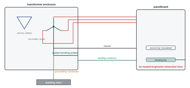
Generators illustrate the importance of this rule. If the transfer switch does not switch the neutral (a three-pole switch on a three-phase four-wire system), the generator neutral remains connected to the utility neutral, the generator is not separately derived, and it must not have its own neutral-to-ground bond. If the transfer switch does switch the neutral (four-pole), the generator is separately derived and must be bonded at the generator. Getting this wrong creates parallel neutral paths and can make ground fault protection at the service trip or fail to trip (Lesson 9).
Sizing bonding conductors
Equipment bonding conductors are sized from the rating of the overcurrent device protecting the circuit, because they must carry the fault current until that device opens.
Table 16 gives the minimum size of field-installed bonding conductors based on the rating or setting of the overcurrent device ahead of the circuit, for copper and aluminium (for example, 12 AWG copper for 20 A, 10 AWG for 60 A, 8 AWG for 100 A, 6 AWG for 200 A, and larger sizes for larger devices). Grounding conductor sizes for services and separately derived systems are in Table 17, based on the size of the largest service or derived conductor.
Worked problem
Bonding conductor for a feeder
A 400 A feeder uses parallel sets of conductors in two separate raceways. Using Table 16, the bonding conductor for a 400 A device is 3 AWG copper. What bonding conductor is needed in each raceway?
Show solution
- Where parallel conductors run in separate raceways, a bonding conductor is installed in each raceway.
- Each must be the full size required for the overcurrent device protecting the feeder, because a fault in one raceway sends all the fault current through that raceway's bonding conductor.
Answer: A full-size 3 AWG copper bonding conductor in each raceway, not half the size. Undersizing parallel bonding conductors is a common error.
Raceways, cable armour and other bonding paths
Metal raceways such as rigid conduit and EMT, and the armour of some cables, are permitted to serve as the bonding path when properly installed with tight, listed fittings, and metal enclosures connected by them are bonded through them. In practice, many engineers and owners specify a separate copper bonding conductor in every raceway anyway, because set-screw fittings loosen, raceways corrode and joints are disturbed by later work, and a wire conductor is more reliable. Flexible metal conduit and liquidtight conduit can serve as bonding paths only in short lengths and smaller sizes; for longer runs, flexible connections to vibrating equipment, and PVC conduit, a bonding conductor is required. Cable types such as TECK90 and MC cable include a bonding conductor inside the cable.
Bonding piping, structural steel and other metal
Metal systems that could become energized must be bonded so that they are at the same potential as the electrical system and fault current has a path back to the source. These include metal water piping, gas piping (bonded as required by the gas and electrical codes), other metal piping, exposed structural steel that is interconnected, metal ductwork in some cases, and metal raised floors in computer rooms. Bonding jumpers are sized according to the code tables and connected with listed clamps. Lightning protection systems must be bonded to the electrical grounding system so that a lightning strike does not create dangerous voltage differences between them.
Grounding electrodes
The grounding electrode system connects the electrical system to earth. In commercial buildings it typically combines several electrodes bonded together: concrete-encased electrodes (reinforcing steel or a bare copper conductor in the footings, often called an Ufer ground), metal underground water piping (supplemented by other electrodes, since plastic piping may later replace it), driven rods, ground rings around the building, and building structural steel where it is effectively grounded. Interconnecting electrodes lowers the resistance to earth and provides redundancy.
The resistance of a single driven rod depends strongly on soil resistivity; in average soil, a 3 m rod might measure 25 to 100 Ω. Codes accept a single rod in some cases only if its resistance is low enough, and otherwise require a second rod at least a minimum distance away. Facilities with sensitive equipment, telecommunications or lightning protection often specify a target of 5 Ω or less for the grounding system, achieved with ground rings, multiple rods, deep electrodes or chemical rods. Resistance is measured with the fall-of-potential method, which injects current between the electrode under test and a remote current probe and measures voltage at a series of potential probe positions, or with clamp-on testers on multiply grounded systems.
Worked problem
Parallel ground rods
A single 3 m rod measures 60 Ω. A second rod is driven 6 m away. If rods spaced at least twice their length interact little, estimate the combined resistance. What about four rods?
Show solution
- Two rods in parallel with little interaction: about \(60/2 = 30\) Ω, in practice somewhat more (perhaps 32 to 35 Ω) because their zones of influence overlap.
- Four rods: ideally 15 Ω; in practice about 18 to 20 Ω.
Answer: Adding rods gives diminishing returns, because each additional rod shares the surrounding soil. To reach 5 Ω in such soil, designers use a ground ring, a grid in the footing, or deeper electrodes reaching moist soil, rather than many short rods.
Isolated grounding and sensitive equipment
Isolated grounding (IG) receptacles have their grounding terminal insulated from the mounting yoke and connected by a separate insulated conductor back to the panel or source, intended to reduce electrical noise on equipment grounding. They must still be connected to the same grounding system at the source; isolated grounding never means connecting equipment to a separate ground rod, which would create a dangerous voltage difference during faults and lightning. Modern electronic equipment is far less sensitive to grounding noise than the equipment for which IG circuits were popularized, and most data centres now use a well-bonded, equipotential approach (signal reference grids and comprehensive bonding of racks and structure) instead of isolated grounds.
Inspection and testing
Common grounding and bonding deficiencies found by inspectors include missing or loose main and system bonding jumpers, neutral-to-ground connections in subpanels, missing bonding conductors in PVC and flexible conduit, undersized parallel bonding conductors, missing bonding of water and gas piping, painted surfaces under bonding connections, and grounding electrodes not interconnected. Testing during commissioning includes continuity of bonding conductors, insulation resistance between neutral and ground with the main bonding jumper temporarily removed (or checking for neutral current on bonding conductors with a clamp meter in service), ground fault protection testing by primary injection where required, and electrode resistance measurement.
Common mistakes
MistakeBonding neutral to ground in downstream panels.
InsteadBond only at the service or the separately derived system source.
MistakeRelying on the earth to clear ground faults.
InsteadProvide a low-impedance bonding path back to the source.
MistakeInstalling a neutral bond at a generator connected through a three-pole transfer switch.
InsteadBond the generator only if the transfer switch switches the neutral.
MistakeUsing half-size bonding conductors in parallel raceways.
InsteadInstall a full-size bonding conductor in each raceway.
MistakeConnecting isolated-ground equipment to a separate ground rod.
InsteadIsolated grounds must return to the same source grounding point.
Summary and key terms
- Grounding limits voltage to earth; bonding provides a low-impedance fault path and equalizes potential.
- Fault current depends on the whole loop impedance; long or poor bonding paths can prevent quick tripping.
- Solidly grounded systems trip on the first fault; high-resistance grounded systems alarm and keep running.
- The neutral is bonded to ground only at the service and at each separately derived system.
- Transformers and generators with switched neutrals are separately derived and need their own bonding and grounding.
- Bonding conductors are sized from the overcurrent device rating, full size in each parallel raceway, and increased for voltage drop.
- Electrode systems interconnect several electrodes; rod resistance has diminishing returns and is measured by fall of potential.
- Grounding
- Connection of a system or equipment to earth.
- Bonding
- Connection of metal parts to form a continuous low-impedance path.
- Main bonding jumper
- The connection between the neutral and the bonding system at the service.
- System bonding jumper
- The neutral-to-enclosure connection at a separately derived system.
- Separately derived system
- A source with no direct connection to another system's supply conductors.
- High-resistance grounding
- Grounding through a resistor that limits fault current to a few amperes.
- Objectionable current
- Neutral current flowing on bonding paths because of improper connections.
- Grounding electrode
- A conductor in contact with earth, such as a rod or footing steel.
- Fall-of-potential test
- A method of measuring electrode resistance using remote probes.
- Isolated grounding receptacle
- A receptacle with its grounding terminal insulated from its yoke.
Practice problems
Work each problem on paper first, then reveal the answer to check.
Can earth clear a ground fault?
Show answer
No; earth resistance is too high; a bonding path is needed.
Fault current for 120 V across 0.6 Ω loop resistance?
Show answer
200 A.
What happens on the first ground fault in an HRG system?
Show answer
An alarm; the system keeps running.
Where is the neutral bonded to ground in a building?
Show answer
At the service and at each separately derived system source.
Is a generator with a three-pole transfer switch separately derived?
Show answer
No; its neutral is solidly connected to the utility neutral.
Bonding conductor for a 100 A circuit (copper)?
Show answer
8 AWG.
Two parallel raceways for a 600 A feeder: bonding conductor size in each?
Show answer
The full size for 600 A in each raceway.
Why add bonding conductors in PVC conduit?
Show answer
PVC does not conduct; there is no other bonding path.
Why do additional ground rods give diminishing returns?
Show answer
Their zones of influence in the soil overlap.
Where must an isolated ground conductor terminate?
Show answer
At the same source grounding point as the system.
Lesson quiz · 5 questions
Score 60% or more to complete this lesson.
Create a free account to save your progress, take quizzes and earn a certificate.