
ELEC-220 · Lesson 5 of 12 · 33 min
Hazardous locations
Wherever flammable gases, vapours, combustible dusts or fibres can be present in the air in dangerous amounts, an ordinary switch, motor or light fixture can become an ignition source. Refineries, gas plants, paint booths, fuel stations, grain elevators, sawmills, distilleries, pharmaceutical plants, wastewater facilities and battery rooms all contain such areas. Electrical work in hazardous (classified) locations follows special code rules: the area is first classified by the likelihood and type of hazard, and then equipment and wiring methods are chosen that cannot ignite the atmosphere. This lesson covers the fire triangle and explosive limits, area classification in the zone and division systems, gas and dust groups, temperature codes, protection techniques and markings, wiring methods and seals, and common applications.
Hazardous locations are covered by Section 18 of the CEC, which uses the zone system (Zones 0, 1 and 2 for gases and vapours, and Zones 20, 21 and 22 for combustible dusts), with Annex J providing the class and division system for use where permitted. Section 20 covers flammable liquid dispensing and related occupancies.
How explosions happen
An explosion needs three things: fuel (a flammable gas, vapour, mist or dust) mixed with an oxidizer (usually air) in the right proportions, and an ignition source with enough energy. Removing any one prevents it. Electrical equipment can ignite atmospheres through arcs and sparks (switches, relays, motor brushes, loose connections, faults) and through hot surfaces (lamps, motors, resistors, heaters).
A flammable gas or vapour burns only between its lower explosive limit (LEL) and upper explosive limit (UEL): below the LEL the mixture is too lean, above the UEL too rich.
| Substance | LEL (% by volume) | UEL (% by volume) | Autoignition temperature | Gas group (zone / division) |
|---|---|---|---|---|
| Methane (natural gas) | 5.0 | 15 | 600 °C | IIA / D |
| Propane | 2.1 | 9.5 | 450 °C | IIA / D |
| Gasoline vapour | about 1.4 | about 7.6 | about 280 °C | IIA / D |
| Ethylene | 2.7 | 36 | 450 °C | IIB / C |
| Hydrogen | 4.0 | 75 | 560 °C | IIC / B |
| Acetylene | 2.5 | 100 | 305 °C | IIC / A |
Worked problem
Hydrogen in a battery room
Lead-acid batteries release hydrogen when charging. A battery room of 120 m³ receives hydrogen at 0.02 m³/h during equalizing charge. With no ventilation, how long until the room reaches 25% of the LEL (1% hydrogen), a common alarm point? What ventilation rate keeps it below 1%?
Show solution
- Hydrogen for 1%: \(0.01 \times 120 = 1.2\) m³; time \(= 1.2/0.02 = 60\) h.
- Steady state concentration \(= \) generation/ventilation; for 1%: ventilation \(= 0.02/0.01 = 2\) m³/h.
Answer: About 60 hours without ventilation, and only 2 m³/h of ventilation keeps it below 1%, but ventilation is required continuously and designs include large safety margins. Battery rooms with adequate ventilation (designed to standards such as IEC 62485, DCE-340) are usually not classified as hazardous locations; without it, part of the room may need classification.
Area classification
Classifying an area means determining what hazardous material may be present and how likely it is to be present in ignitable concentrations. Classification is an engineering task, usually done by a qualified person with process knowledge, and documented on area classification drawings that show the boundaries of each zone or division. Guidance comes from standards and recommended practices (for example IEC 60079-10-1, API RP 505 and RP 500, NFPA 497 and 499).
| Zone (gases) | Division equivalent | Likelihood of explosive atmosphere |
|---|---|---|
| Zone 0 | Division 1 (part) | Present continuously or for long periods (inside tanks, above liquid surfaces) |
| Zone 1 | Division 1 (part) | Likely in normal operation (around vents, open dispensing) |
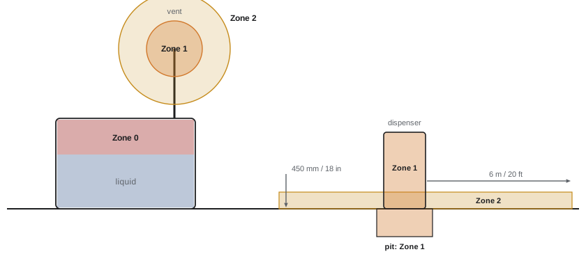
| Zone 2 | Division 2 | Not likely in normal operation, and if it occurs only for a short time (leaks from failed seals or gaskets) |
The size of each zone depends on the release rate, the substance's density (heavier-than-air vapours such as gasoline and propane spread along the ground and into pits), ventilation and the surroundings. Good ventilation can reduce the extent of a zone or downgrade it; pits and trenches below a classified area often become Zone 1 because vapours collect there.
Gas groups and dust groups
Gases differ in how easily they ignite and how easily a flame passes through narrow gaps, so equipment is tested and marked for the gas groups it is suitable for:
- Zone system: Group IIA (propane, gasoline, methane in surface industry), IIB (ethylene and similar), IIC (hydrogen, acetylene). Equipment marked IIC is suitable for IIB and IIA; IIB for IIA.
- Division system: Class I Groups A (acetylene), B (hydrogen), C (ethylene), D (propane, gasoline). Group A is the most severe.
- Dusts: Groups IIIA (combustible flyings), IIIB (non-conductive dust) and IIIC (conductive dust) in the zone system; Class II Groups E (metal dusts), F (carbonaceous dusts such as coal) and G (grain, flour, plastics) in the division system, and Class III for fibres and flyings.
Temperature codes
Hot surfaces can ignite a gas if they reach its autoignition temperature. Equipment is marked with a temperature code (T-code) giving its maximum surface temperature in the specified ambient (usually 40 °C), which must be below the autoignition temperature of the gases present.
| T-code | Maximum surface temperature |
|---|---|
| T1 | 450 °C |
| T2 | 300 °C |
| T3 | 200 °C |
| T4 | 135 °C |
| T5 | 100 °C |
| T6 | 85 °C |
Worked problem
Selecting a temperature code
A luminaire will be installed where gasoline vapour (autoignition about 280 °C) and diethyl ether (autoignition about 160 °C) may be present. What is the minimum T-code?
Show solution
- The surface temperature must be below the lowest autoignition temperature, 160 °C.
- T3 (200 °C) exceeds 160 °C; T4 (135 °C) is below it.
Answer: T4 or better (T5, T6). The equipment must also suit the gas group of each substance and the ambient temperature at the installation, since T-codes are given for a specified ambient.
Protection techniques and markings
Equipment for hazardous locations prevents ignition in one of several ways, identified in the zone system by Ex protection codes:
| Technique | Code | Principle | Permitted in |
|---|---|---|---|
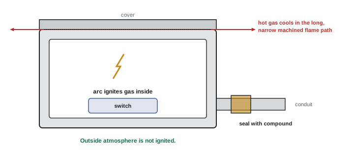
| Flameproof (explosion-proof) | Ex d (Div: explosion-proof) | Enclosure contains an internal explosion; flame paths cool escaping gases | Zone 1 and 2 (Div 1 and 2) |
| Increased safety | Ex e | No arcing parts; extra measures against excess temperature and sparks | Zone 1 and 2 |
| Intrinsic safety | Ex ia / ib | Circuit energy limited below what can ignite the gas, even with faults | ia: Zone 0, 1, 2; ib: Zone 1, 2 |
| Pressurization (purging) | Ex p | Enclosure kept at positive pressure with clean air or inert gas | Zone 1 and 2 |
| Encapsulation | Ex m | Ignition sources sealed in compound | Zone 0 to 2 depending on level |
| Non-sparking | Ex nA, nC (now Ex ec) | Normal operation does not produce ignition sources | Zone 2 (Div 2) |
| Dust ignition protection | Ex t | Enclosure excludes dust and limits surface temperature | Zones 20 to 22 |
Equipment protection levels (EPLs) summarize suitability: Ga, Gb and Gc for gas Zones 0, 1 and 2, and Da, Db and Dc for dust Zones 20, 21 and 22. A typical zone marking reads like "Ex db IIB T4 Gb": flameproof, Group IIB, temperature class T4, suitable for Zone 1. Equipment must be certified (or listed) by an accredited body, and installed and maintained so that its protection is not compromised: a flameproof enclosure with a missing bolt, scratched flame path or wrong cable gland is no longer flameproof.
Worked problem
Reading a marking
A junction box is marked "Ex eb IIC T6 Gb". Can it be used in a Zone 1 area where hydrogen is present, and in a Zone 0 area?
Show solution
- Ex eb: increased safety, level b, suitable for Zone 1.
- IIC covers hydrogen; T6 (85 °C) is far below hydrogen's autoignition temperature.
- EPL Gb is suitable for Zones 1 and 2, but not Zone 0, which requires Ga.
Answer: Yes for Zone 1 with hydrogen; no for Zone 0. Only equipment at protection level Ga (such as intrinsically safe Ex ia equipment) may be used in Zone 0.
Intrinsic safety
Intrinsically safe (IS) circuits are the preferred method for instrumentation: sensors, transmitters and switches in the hazardous area are powered through barriers or isolators in the safe area that limit voltage and current so that no spark or hot surface in the field circuit can ignite the gas, even with faults. Because the energy is limited, ordinary wiring methods may be used in the hazardous area, but IS circuits must be separated from other circuits, identified (often with light blue cable or labels), and the combined capacitance and inductance of cables and devices must stay within the barrier's permitted values (the entity concept).
Worked problem
Entity check
An IS barrier allows a maximum external capacitance of 150 nF. A transmitter has internal capacitance of 20 nF, and the cable has 120 pF/m. What is the maximum cable length?
Show solution
- Capacitance available for the cable: \(150 - 20 = 130\) nF.
- Length: \(130{,}000\) pF \(/120\) pF/m \(= 1083\) m.
Answer: About 1080 m. Similar checks apply to inductance (or the L/R ratio). Exceeding these values allows enough stored energy to ignite the gas.
Wiring methods and seals
In Zone 1 and Division 1 areas, wiring is typically threaded rigid metal conduit with explosion-proof fittings, or cables certified for the location (such as armoured cables with suitable glands). Conduits connected to flameproof enclosures must be sealed to stop gases and flames travelling along the conduit and to prevent pressure piling (an explosion in one enclosure precompressing gas in the next). Seals are fittings filled with a special compound after the conductors are installed.
Section 18 requires seals in conduit entering flameproof enclosures that contain arcing or high-temperature devices, located as close as practicable and in any case within 450 mm of the enclosure, and seals where conduit leaves a classified area. Threaded joints in flameproof systems need at least five full threads engaged. Cable glands must be certified for the zone and gas group.
Worked problem
Seal location
An explosion-proof motor starter enclosure in a Division 1 (or Zone 1) area has a 1-inch (27 mm) conduit entry. The installer plans to place the seal fitting 600 mm (24 in) away, after a union and an elbow. Is this acceptable?
Show solution
- The maximum distance is 450 mm (18 in) from the enclosure.
- Only explosion-proof unions, couplings, reducers and elbows of specified types may lie between the seal and the enclosure.
Answer: No: 600 mm exceeds the 450 mm (18 in) limit. The seal must be moved closer, and the fittings between it and the enclosure must be of the permitted explosion-proof types. After pulling conductors, the seal must be dammed and filled with compound, a step that is often forgotten.
Common applications
Electricians encounter hazardous locations in many settings:
- Fuel dispensing: Section 20 classifies areas around dispensers, vents and fill points; the space within a dispenser enclosure is Zone 1, and a layer near grade extending about 6 m horizontally from the dispenser and up to 450 mm above grade is Zone 2, with emergency shut-off switches required.
- Commercial garages and repair shops: areas near the floor and in pits where gasoline vapours collect.
- Spray booths and finishing rooms, with flammable paints and solvents.
- Grain, flour, sugar, plastics, wood and metal processing, where combustible dust accumulates; dust explosions can be devastating because an initial blast raises more dust.
- Oil and gas production, refineries, chemical plants and pipelines.
- Data centres: generator fuel day tanks and fuel rooms, and battery rooms, are reviewed for classification; with proper design and ventilation they are usually unclassified, but the analysis must be documented.
Lesson 6 covers the grounding and bonding principles on which hazardous location bonding requirements build.
Common mistakes
MistakeAssuming equipment marked for Zone 1 or Division 2 can be used anywhere.
InsteadCheck zone or division, gas group, temperature code and EPL for each location.
MistakeChoosing T-codes from the most common gas only.
InsteadUse the lowest autoignition temperature of all substances present.
MistakeLeaving seals unfilled or placing them too far from enclosures.
InsteadInstall within 450 mm (18 in) and fill with compound after pulling conductors.
MistakeOpening flameproof enclosures while energized or damaging flame paths.
InsteadDe-energize, check for gas, protect machined surfaces and replace all bolts.
MistakeMixing intrinsically safe and non-IS wiring.
InsteadSeparate and identify IS circuits and verify entity parameters.
Summary and key terms
- Explosions need fuel between the LEL and UEL, oxygen and an ignition source.
- CEC Section 18 uses Zones 0, 1, 2 (gases) and 20, 21, 22 (dusts); Annex J covers divisions.
- Classification depends on how likely and how often an explosive atmosphere is present.
- Gas groups IIA, IIB, IIC (Groups D, C, B, A) and dust groups describe ignition severity.
- T-codes must be below the lowest autoignition temperature present.
- Protection techniques include flameproof, increased safety, intrinsic safety, pressurization, encapsulation and non-sparking.
- EPLs Ga/Gb/Gc and Da/Db/Dc match equipment to zones.
- Seals within 450 mm (18 in), five full threads and certified glands keep flameproof systems effective.
- Hazardous location
- An area where flammable gases, vapours, dusts or fibres may be present in ignitable amounts.
- Lower explosive limit
- The minimum concentration of a fuel in air that can burn.
- Autoignition temperature
- The lowest temperature at which a substance ignites without a spark or flame.
- Zone 1
- An area where an explosive gas atmosphere is likely in normal operation.
- Division 2
- An area where an explosive atmosphere is not likely in normal operation.
- Gas group
- A classification of gases by ignition and flame-transmission properties.
- Temperature code
- The maximum surface temperature class of equipment.
- Flameproof enclosure
- An enclosure that contains an internal explosion without igniting the surroundings.
- Intrinsic safety
- Protection by limiting circuit energy below ignition levels.
- Equipment protection level
- A rating (Ga, Gb, Gc, Da, Db, Dc) of equipment suitability by zone.
- Conduit seal
- A compound-filled fitting that prevents gas and flame passage along a conduit.
Practice problems
Work each problem on paper first, then reveal the answer to check.
What three elements must be present for an explosion?
Show answer
Fuel in the flammable range, an oxidizer (air) and an ignition source.
Propane LEL is 2.1%. What concentration is 20% of the LEL?
Show answer
0.42%.
Define Zone 0, Zone 1 and Zone 2.
Show answer
Continuously or long periods; likely in normal operation; not likely and only briefly.
Which gas group includes hydrogen?
Show answer
IIC (Class I Group B).
A gas has an autoignition temperature of 230 °C. Lowest suitable T-code?
Show answer
T3 (200 °C).
What does "Ex db IIB T4 Gb" mean?
Show answer
Flameproof, gas group IIB, maximum surface 135 °C, suitable for Zone 1.
Which protection method is preferred for instrumentation, and why?
Show answer
Intrinsic safety; it limits energy so even faults cannot ignite gas, and permits ordinary wiring and live work.
Barrier Co = 200 nF, device Ci = 30 nF, cable 100 pF/m. Maximum length?
Show answer
1700 m.
Maximum distance from an explosion-proof enclosure to its seal?
Show answer
450 mm (18 in).
Why do pits below classified areas often become Zone 1?
Show answer
Heavier-than-air vapours collect in low points.
Lesson quiz · 5 questions
Score 60% or more to complete this lesson.
Create a free account to save your progress, take quizzes and earn a certificate.