
ELE-380 · Lesson 2 of 12 · 30 min
Per-unit analysis
A power system contains many voltage levels linked by transformers: a generator at 13.8 kV, transmission at 230 kV, subtransmission at 69 kV, distribution at 25 kV or 12.47 kV, and buildings at a few hundred volts. Analysing such a network in volts, amperes and ohms means referring every impedance across every transformer with the square of its turns ratio, a tedious and error-prone process. The per-unit system removes this burden. Every quantity is expressed as a fraction of a chosen base value, and with bases chosen consistently, ideal transformers disappear from the circuit entirely. Per-unit values also have the useful property that similar equipment has similar per-unit impedances regardless of its size, which makes data easy to check and estimate. This lesson defines the per-unit system, shows how to change bases and handle transformers, and builds the per-unit impedance diagram of a small system.
Base quantities
A per-unit value is an actual value divided by a base value of the same dimension:
In a three-phase system, two base quantities are chosen and the others follow from circuit laws. The usual choice is a three-phase power base \(S_b\) (for example 100 MVA), common to the whole system, and a line-to-line voltage base \(V_b\) for each voltage zone, normally the nominal voltage. Then
These formulas use three-phase power and line-to-line voltage, and they give exactly the same per-unit values as a per-phase calculation with single-phase power \(S_b/3\) and line-to-neutral voltage \(V_b/\sqrt3\). In per unit, the factor \(\sqrt3\) vanishes from the power formula: \(S_{\mathrm{pu}} = V_{\mathrm{pu}}I_{\mathrm{pu}}^*\), whether the system is single-phase or three-phase.
Worked problem
Base values
For a 100 MVA base, find the base current and base impedance at 230 kV and at 13.8 kV. A 230 kV line has a reactance of 45 Ω; what is it in per unit?
Show solution
- At 230 kV: \(I_b = 100 \times 10^6/(\sqrt3 \times 230{,}000) = 251\) A; \(Z_b = 230^2/100 = 529\) Ω.
- At 13.8 kV: \(I_b = 100 \times 10^6/(\sqrt3 \times 13{,}800) = 4184\) A; \(Z_b = 13.8^2/100 = 1.904\) Ω.
- Line: \(X = 45/529 = 0.0851\) pu.
Answer: Base current 251 A and 4184 A, base impedance 529 Ω and 1.904 Ω; the line reactance is 0.085 pu. Note the convenient form \(Z_b = V_b^2(\mathrm{kV})/S_b(\mathrm{MVA})\) in ohms.
Changing base
Equipment impedances are given on the equipment's own rating as base: a transformer nameplate might state "7.5% impedance" on its 2.5 MVA rating and rated voltages. To combine them in a system study, every impedance must be converted to the common system base. Since the ohmic value is the same,
When the voltage bases agree, as is usually arranged, only the power ratio matters: a 0.075 pu impedance on 2.5 MVA becomes \(0.075 \times 100/2.5 = 3.0\) pu on 100 MVA. Small equipment has large per-unit impedances on a large system base, reflecting its small capacity.
Worked problem
Fault current at a transformer secondary
A 2.5 MVA, 25 kV to 600 V transformer has an impedance of 7.5%. Assuming the utility supply is infinite (zero impedance), what is the three-phase fault current at the 600 V terminals?
Show solution
- On the transformer base, a bolted fault at the secondary with 1.0 pu source voltage gives \(I_{\mathrm{pu}} = 1/0.075 = 13.3\) pu.
- Base current at 600 V: \(2.5 \times 10^6/(\sqrt3 \times 600) = 2406\) A.
- Fault current: \(13.3 \times 2406 = 32{,}100\) A.
Answer: About 32 kA. The real value is somewhat lower because the utility source has impedance, but this "infinite bus" estimate is a quick upper bound used to check equipment ratings.
Transformers in per unit
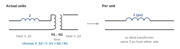
Consider a single-phase transformer with turns ratio \(N_1 : N_2\) and leakage impedance \(Z\) referred to the primary. Referred to the secondary, the impedance is \(Z(N_2/N_1)^2\). If the voltage bases on the two sides are chosen in the ratio of the turns, \(V_{b2}/V_{b1} = N_2/N_1\), then the base impedances are in the ratio \((N_2/N_1)^2\) too, so the per-unit impedance is the same on both sides:
The ideal transformer becomes a 1:1 ratio in per unit and can be removed from the circuit, leaving only its series impedance (and, if needed, a shunt magnetizing branch, usually neglected in system studies). This is the main reason for using per unit. The procedure is to pick the voltage base in one zone and carry it through each transformer by its rated voltage ratio, so that every zone has a consistent base.
Three-phase transformer connections
For three-phase transformers, the voltage base ratio is the ratio of rated line-to-line voltages, whatever the winding connection, and the per-unit impedance on the transformer's own three-phase rating is the nameplate percentage impedance. Wye-delta transformers also introduce a 30° phase shift between primary and secondary line voltages (the North American convention is that the high-voltage side leads). In balanced load flow and three-phase fault studies the shift can be ignored, since it shifts all quantities on one side equally, but it matters for paralleling transformers, which must have the same phase shift, and in the unbalanced fault analysis of Lesson 9.
Off-nominal taps
Most power transformers have taps that change the ratio by up to about ±10% in steps of 0.625% to 2.5%, to regulate voltage. If the actual ratio differs from the ratio of the voltage bases, the transformer is represented by its per-unit impedance in series with an ideal transformer of ratio \(a\):1, where \(a\) is the off-nominal ratio (for example 1.025 for a +2.5% tap). For load flow, this combination is converted to an equivalent π circuit whose elements depend on \(a\), and the tap ratio can be adjusted automatically to hold a bus voltage, as Lesson 6 describes.
Three-winding transformers
A three-winding transformer (for example 230/69/13.8 kV) is represented by a wye of three impedances \(Z_p\), \(Z_s\) and \(Z_t\). Test data give the impedances between pairs of windings, \(Z_{ps}\), \(Z_{pt}\) and \(Z_{st}\), each measured with the third winding open and all converted to a common base, from which
One of the three can come out slightly negative; it is a mathematical equivalent, not a physical component.
Typical per-unit values
On their own ratings, equipment impedances fall into narrow ranges, which makes per unit a powerful check on data: a transformer with "75% impedance" is clearly a typing error.
| Equipment | Quantity | Typical value (pu on own rating) |
|---|---|---|
| Power transformer, 10 to 500 MVA | Leakage reactance | 0.06 to 0.15 |
| Distribution transformer | Impedance | 0.02 to 0.06 |
| Synchronous generator | Subtransient reactance \(X_d''\) | 0.12 to 0.25 |
| Synchronous generator | Transient reactance \(X_d'\) | 0.20 to 0.35 |
| Synchronous generator | Synchronous reactance \(X_d\) | 1.0 to 2.0 |
| Induction motor | Locked-rotor reactance | 0.15 to 0.25 |
| Overhead line, 230 kV, 100 km (100 MVA base) | Series reactance | about 0.09 |
Building a per-unit impedance diagram
The procedure for a system study is:
- Choose a system power base, commonly 100 MVA.
- Choose a voltage base in one zone, usually the nominal voltage, and carry it through each transformer by its rated voltage ratio.
- Convert every impedance to the system base, using the change-of-base formula for equipment data and \(Z/Z_b\) for impedances given in ohms.
- Convert loads to per-unit power (or impedance) and sources to per-unit voltages.
- Draw the per-unit impedance diagram, which is now a single circuit with no transformers, and solve it.
- Convert results back to actual units with the base values of each zone.
Worked problem
A small system in per unit
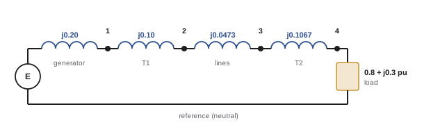
Generator G: 100 MVA, 13.8 kV, \(X_d'' = 0.20\). Transformer T1: 100 MVA, 13.8/230 kV, \(X = 0.10\). Two parallel 230 kV lines, each \(X = 50\) Ω. Transformer T2: 75 MVA, 230/34.5 kV, \(X = 0.08\). Load: 80 MW and 30 Mvar at 34.5 kV. Convert to a 100 MVA system base with 230 kV on the lines.
Show solution
- Voltage bases: 13.8 kV (generator), 230 kV (lines), 34.5 kV (load), consistent with the transformer ratios.
- G and T1 are already on 100 MVA and their rated voltages: \(X_G = 0.20\), \(X_{T1} = 0.10\).
- Lines: \(Z_b = 529\) Ω, each \(X = 50/529 = 0.0945\); in parallel 0.0473.
- T2: \(X = 0.08 \times 100/75 = 0.1067\).
- Load: \(S = (80 + j30)/100 = 0.8 + j0.3\) pu.
Answer: The impedance diagram is a source behind \(j0.20\) (generator), then \(j0.10\), \(j0.0473\) and \(j0.1067\) in series to the load of \(0.8 + j0.3\) pu: a total series reactance of 0.454 pu from the generator internal voltage to the load, or 0.254 pu from the generator terminals.
With the impedance diagram in hand, the load voltage can be found. A constant-power load makes the circuit non-linear, since the current depends on the voltage, so a simple iteration is used: guess the load voltage, compute the current \(I = (S/V)^*\), recompute the voltage drop, and repeat. This is a miniature version of the load flow calculations of Lesson 6.
import numpy as np

S_load = 0.8 + 0.3j          # pu on 100 MVA
X = 0.10 + 0.0473 + 0.1067   # T1 + two lines in parallel + T2, from the generator terminals
V_gen = 1.0                  # generator terminal voltage held at 1.0 pu by its AVR

V = 1.0 + 0j
for it in range(1, 9):
    I = np.conj(S_load / V)
    V = V_gen - 1j * X * I
    print(f"iteration {it}: |V| = {abs(V):.5f} pu, angle = {np.degrees(np.angle(V)):7.3f} deg")

base_kV, base_A = 34.5, 100e6 / (np.sqrt(3) * 34.5e3)
print(f"load voltage = {abs(V) * base_kV:.2f} kV, load current = {abs(I) * base_A:.0f} A")
print(f"reactive power supplied by the generator = {(abs(I) ** 2 * X + S_load.imag) * 100:.1f} Mvar")iteration 1: |V| = 0.94588 pu, angle = -12.405 deg iteration 2: |V| = 0.89609 pu, angle = -12.405 deg iteration 3: |V| = 0.89170 pu, angle = -13.172 deg iteration 4: |V| = 0.88823 pu, angle = -13.172 deg iteration 5: |V| = 0.88790 pu, angle = -13.230 deg iteration 6: |V| = 0.88764 pu, angle = -13.230 deg iteration 7: |V| = 0.88762 pu, angle = -13.234 deg iteration 8: |V| = 0.88760 pu, angle = -13.234 deg load voltage = 30.62 kV, load current = 1611 A reactive power supplied by the generator = 53.5 Mvar
The iteration converges in a few steps, and the voltage at the load settles at about 0.89 pu, an 11% drop that would be unacceptable in practice (service voltages are normally kept within about ±5%). It is driven mainly by the reactive power flowing through the series reactance: the generator must supply 53.5 Mvar: the 30 Mvar of the load plus 23.5 Mvar consumed by the transformers and lines themselves. Adding a capacitor bank at the load bus, or raising the T2 tap, would correct it. Being able to see such problems quickly, without wading through turns ratios, is the payoff of the per-unit system.
Advantages and cautions
Per-unit analysis offers several advantages beyond eliminating transformers: per-unit voltages near 1.0 make abnormal values obvious (a bus at 0.88 pu is clearly low), equipment data can be checked against typical ranges, the \(\sqrt3\) factors disappear, and computer programs work naturally in per unit. The cautions are to choose voltage bases consistently through every transformer (a mismatch silently corrupts results, unless it is represented as an off-nominal tap), to convert all equipment data to the system base before combining them, and to remember which zone's base to use when converting results back.
Lesson 3 uses per-unit values to describe generator reactances and capability, and Lesson 10 extends the transformer models of this lesson to zero-sequence networks and phase shifts.
Common mistakes
MistakeCombining nameplate impedances without converting them to the system base.
InsteadConvert each to the common base with Z_new = Z_old (V_old/V_new)² (S_new/S_old).
MistakeUsing line-to-neutral voltage with a three-phase power base.
InsteadUse line-to-line voltage with three-phase power, or line-to-neutral with per-phase power; the per-unit values are the same.
MistakeChoosing voltage bases that do not follow the transformer ratios.
InsteadCarry the base through each transformer by its rated ratio, or model the difference as an off-nominal tap.
MistakeForgetting to convert results back with the correct zone base.
InsteadEach voltage zone has its own base current and impedance.
MistakeAccepting implausible impedance data.
InsteadCompare with typical per-unit ranges; values far outside them usually indicate an error.
Summary and key terms
- Per-unit value = actual / base; choose S_b (system-wide) and V_b (per zone); I_b = S_b/(√3 V_b), Z_b = V_b²/S_b.
- Three-phase and per-phase calculations give identical per-unit values; √3 disappears.
- Change of base: Z_new = Z_old (V_old/V_new)² (S_new/S_old).
- With voltage bases in the turns ratio, ideal transformers vanish and per-unit impedances are the same on both sides.
- Wye-delta transformers shift phase by 30°; off-nominal taps are modelled by an ideal ratio a and a π equivalent.
- Three-winding transformers use a wye of impedances derived from pairwise test data.
- Typical per-unit values: transformers 0.06 to 0.15, generator X″d 0.12 to 0.25.
- Build the impedance diagram, solve it, and convert results back with each zone's base.
- Per unit
- A quantity expressed as a fraction of a base value.
- Base power
- The three-phase power base, common to the whole system.
- Base voltage
- The line-to-line voltage base of a voltage zone.
- Base impedance
- V_b²/S_b.
- Change of base
- Conversion of a per-unit impedance from one set of bases to another.
- Voltage zone
- Part of a network between transformers, sharing one voltage base.
- Percentage impedance
- Transformer impedance in percent of its own rating base.
- Off-nominal tap
- A transformer ratio different from the ratio of the voltage bases.
- Impedance diagram
- The per-unit equivalent circuit of a system.
- Subtransient reactance
- Generator reactance in the first cycles after a disturbance.
- Three-winding transformer
- A transformer with three windings at different voltages.
- Phase shift
- The angle between line voltages on the two sides of a wye-delta transformer.
Practice problems
Work each problem on paper first, then reveal the answer to check.
Find Z_b and I_b for a 50 MVA base at 69 kV.
Show answer
Z_b = 69²/50 = 95.2 Ω; I_b = 50e6/(√3 × 69,000) = 418 A.
A 20 Ω reactance at 69 kV on a 100 MVA base is how many per unit?
Show answer
Z_b = 47.6 Ω; 20/47.6 = 0.42 pu.
Convert a 0.06 pu impedance on 10 MVA to a 100 MVA base.
Show answer
0.6 pu.
A generator rated 13.2 kV, 50 MVA, X″ = 0.18 is connected in a zone with base 13.8 kV and 100 MVA. Find X″ on the system base.
Show answer
0.18 × (13.2/13.8)² × (100/50) = 0.329 pu.
Why does an ideal transformer vanish in per unit?
Show answer
Its voltage ratio equals the ratio of the voltage bases, so it becomes 1:1 in per unit.
A 1 MVA transformer has 5.75% impedance and a 480 V secondary. Estimate the infinite-bus fault current.
Show answer
I_rated = 1203 A; 1203/0.0575 = 20.9 kA.
Pairwise impedances (common base) are Z_ps = 0.10, Z_pt = 0.12, Z_st = 0.06. Find Z_p, Z_s and Z_t.
Show answer
Z_p = 0.08, Z_s = 0.02, Z_t = 0.04.
A bus voltage is 0.94 pu on a 230 kV base. What is it in kV?
Show answer
216 kV.
Why must paralleled transformers have the same phase shift?
Show answer
Otherwise their secondary voltages differ in angle, driving large circulating currents.
A 0.5 + j0.2 pu load on a 100 MVA base: what are P and Q?
Show answer
50 MW and 20 Mvar.
Lesson quiz · 5 questions
Score 60% or more to complete this lesson.
Create a free account to save your progress, take quizzes and earn a certificate.