
ELE-380 · Lesson 10 of 12 · 28 min
Unbalanced faults in networks
Lesson 9 introduced symmetrical components and the formulas for unbalanced faults given the Thévenin sequence impedances at the fault. Most faults on real systems are unbalanced: single line-to-ground faults make up roughly 70% to 80% of transmission faults, line-to-line and double line-to-ground faults most of the rest, and balanced three-phase faults only a few percent. This lesson builds the sequence networks of a whole system, including the zero-sequence paths set by transformer connections and the phase shifts that transformers introduce, computes fault currents and voltages throughout the network with sequence bus impedance matrices, and treats faults through impedance, open conductors, the effect of grounding on overvoltages, and the standards used in practical short-circuit studies.
Sequence models of components
Each component contributes an impedance to each sequence network:
- Generators: positive-sequence source behind \(X_d''\); negative-sequence reactance close to \(X_d''\); zero-sequence reactance small (0.03 to 0.1 pu), plus \(3Z_n\) for any neutral grounding impedance. Large generators are usually grounded through a high resistance via a distribution transformer, which limits ground fault current to a few amperes, and connected through a delta-wye step-up transformer, so their zero-sequence circuit is isolated from the network.
- Transmission lines: negative-sequence impedance equals positive; zero-sequence impedance is two to four times larger, because zero-sequence current returns through the earth and shield wires, enclosing a much larger loop. Zero-sequence mutual coupling between parallel lines on the same towers can be significant.
- Transformers: positive- and negative-sequence impedance equal the leakage impedance, but the zero-sequence path depends on the winding connections.
- Loads: usually neglected in fault studies, except large motor loads, which contribute fault current for a few cycles.
Transformer connections in the zero-sequence network
Zero-sequence currents are equal in all three phases, so they can flow in a winding only if there is a return path. A grounded wye winding provides one through its neutral; an ungrounded wye does not; a delta winding lets zero-sequence currents circulate inside the delta but not flow in the lines connected to it. The resulting zero-sequence equivalents are:
| Connection (side P – side S) | Zero-sequence equivalent |
|---|---|
| Grounded wye – grounded wye | series impedance connecting P and S, as in positive sequence |
| Grounded wye – delta | P connected to the reference bus through the transformer impedance; S open |
| Ungrounded wye – delta | open on both sides |
| Delta – delta | open on both sides |
| Grounded wye – ungrounded wye | open on both sides (no path on the ungrounded side) |
| Neutral grounded through \(Z_n\) | add \(3Z_n\) in series on that side |
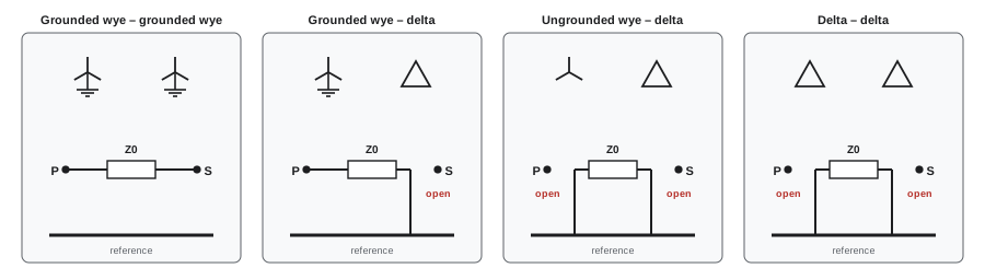
The grounded wye – delta connection is the most important in practice. Seen from the wye side it is a ground source: a ground fault on the wye side draws zero-sequence current through the transformer even when nothing is connected to the delta side. Grounding transformers (zigzag or wye-delta units) use exactly this property to create a ground reference on otherwise ungrounded systems.
Transformers with a wye-delta connection also shift phase: in North American practice (ANSI), the high-voltage positive-sequence quantities lead the low-voltage ones by 30°, and negative-sequence quantities are shifted by the same angle in the opposite direction. The shift does not change current magnitudes in each sequence network, but it changes how sequence quantities recombine into phase quantities on the other side of the transformer.
Fault analysis with sequence bus impedance matrices
For a network with many buses, the positive-, negative- and zero-sequence bus impedance matrices \(Z^{(1)}\), \(Z^{(2)}\) and \(Z^{(0)}\) are built by inverting each sequence admittance matrix (Lesson 9). The diagonal element at the fault bus \(k\) is the Thévenin impedance of each sequence network there. For a single line-to-ground fault through fault impedance \(Z_f\):
The sequence voltages at any other bus \(i\) during the fault follow from superposition, since the fault injects \(-I\) at bus \(k\) into each sequence network:
The sequence current in any branch is the difference of sequence voltages at its ends divided by its sequence impedance. Phase quantities are then recovered with the symmetrical component transformation, applying the transformer phase shifts for buses on the far side of wye-delta transformers.
Worked problem
Ground fault at a substation
At a 138 kV bus, the sequence Thévenin impedances are \(Z_1 = Z_2 = j0.08\) pu and \(Z_0 = j0.12\) pu on 100 MVA. Find the single line-to-ground fault current for a bolted fault and for a fault through 5 Ω.
Show solution
- Base current: \(100{,}000/(\sqrt3 \times 138) = 418\) A. Base impedance: \(138^2/100 = 190.4\) Ω, so \(5\) Ω \(= 0.0263\) pu.
- Bolted: \(I_a = 3/(0.08 + 0.08 + 0.12) = 3/0.28 = 10.7\) pu \(= 4.48\) kA.
- Through 5 Ω: \(3Z_f = 0.0788\) pu (resistive). \(|I_a| = 3/|0.0788 + j0.28| = 3/0.291 = 10.3\) pu \(= 4.31\) kA.
Answer: 4.48 kA bolted and 4.31 kA through 5 Ω. At transmission level a few ohms of fault resistance changes the current only slightly. On distribution systems the picture is different: the base impedance is much smaller, so the same fault resistance is far larger in per unit, and high-impedance faults (a conductor lying on dry ground or pavement) can draw so little current that overcurrent protection cannot see them.
import numpy as np

a = np.exp(2j * np.pi / 3)
A = np.array([[1, 1, 1], [1, a ** 2, a], [1, a, a ** 2]])
# Bus 1: generator terminals, X1 = X2 = 0.20 (its zero-sequence circuit is isolated by the delta winding)
# Bus 1 - bus 2: delta (generator side) to grounded-wye step-up transformer, X = 0.10
# Bus 2 - bus 3: line, X1 = X2 = 0.15, X0 = 0.45; bus 3 also fed from a grid equivalent X1 = X2 = 0.25, X0 = 0.20
def zbus(y_branches, n=3):
    Y = np.zeros((n, n), complex)
    for i, j, z in y_branches:
        y = 1 / z
        if j is None: Y[i, i] += y
        else:
            Y[i, i] += y; Y[j, j] += y; Y[i, j] -= y; Y[j, i] -= y
    return np.linalg.inv(Y)

Z1 = zbus([(0, None, 0.20j), (0, 1, 0.10j), (1, 2, 0.15j), (2, None, 0.25j)])
Z0 = np.zeros((3, 3), complex)                         # zero sequence: bus 1 is isolated by the delta winding
Z0[1:, 1:] = zbus([(0, None, 0.10j), (0, 1, 0.45j), (1, None, 0.20j)], n=2)   # grounded wye appears at bus 2
Z2 = Z1.copy()
k = 2                                                  # single line-to-ground fault at bus 3
I0 = 1.0 / (Z1[k, k] + Z2[k, k] + Z0[k, k])
print(f"Thevenin at bus 3: Z1 = {Z1[k, k].imag:.4f}, Z0 = {Z0[k, k].imag:.4f} pu; fault current 3 I0 = {abs(3 * I0):.2f} pu")
print(f"three-phase fault current at bus 3 for comparison: {abs(1 / Z1[k, k]):.2f} pu")
for bus in (0, 1, 2):
    V1 = 1 - Z1[bus, k] * I0; V2 = -Z2[bus, k] * I0
    V0 = -Z0[bus, k] * I0
    if bus == 0:                                       # sequence quantities shift by +/-30 deg across the delta-wye
        V1 *= np.exp(-1j * np.pi / 6); V2 *= np.exp(1j * np.pi / 6)
    Vabc = A @ np.array([V0, V1, V2])
print(f"bus {bus + 1}: |Va| = {abs(Vabc[0]):.2f}, |Vb| = {abs(Vabc[1]):.2f}, |Vc| = {abs(Vabc[2]):.2f} pu")Thevenin at bus 3: Z1 = 0.1607, Z0 = 0.1467 pu; fault current 3 I0 = 6.41 pu three-phase fault current at bus 3 for comparison: 6.22 pu bus 1: |Va| = 0.78, |Vb| = 0.78, |Vc| = 1.00 pu bus 2: |Va| = 0.49, |Vb| = 0.93, |Vc| = 0.93 pu bus 3: |Va| = 0.00, |Vb| = 0.99, |Vc| = 0.99 pu
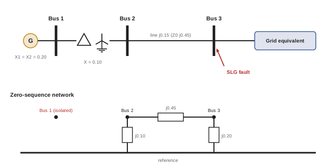
Three features of the result deserve attention. First, the ground fault current exceeds the three-phase fault current, because the grounded-wye transformer and the grid equivalent make the zero-sequence impedance smaller than the positive-sequence impedance; breakers near strong ground sources must be checked for single-phase duty. Second, at bus 2 the faulted phase dips to about half voltage while the other two stay near normal. Third, at the generator, on the delta side of the step-up transformer, the ground fault appears as a dip in two phases with the third normal: the zero-sequence component cannot pass the delta, and the phase shift redistributes the remaining components. Customers fed through delta-wye distribution transformers see sags of this two-phase type from single-phase faults upstream, which affects how sensitive equipment rides through them.
Faults through impedance and arcs
Real faults are rarely bolted. An arc between a conductor and a tower has a resistance that depends on its length and current; the Warrington formula, \(R_{\text{arc}} \approx 28{,}700L/I^{1.4}\) Ω (with \(L\) in metres and \(I\) in amperes), gives a few ohms for typical transmission flashovers. Faults to ground through trees, poles or soil add tower footing or ground resistance of a few to tens of ohms. Fault impedance matters most for protection: distance relays see the fault resistance as extra apparent impedance, which can make an in-zone fault look farther away, and ground overcurrent relays on distribution feeders must be sensitive enough to see high-impedance faults.
Open-conductor faults
Not all faults are short circuits. A broken conductor, a blown fuse in one phase or a breaker pole that fails to close creates an open-phase condition, a series fault. For one open phase between points \(p\) and \(q\), the analysis looks into the network from the break: the positive-, negative- and zero-sequence impedances between \(p\) and \(q\) are connected in parallel at the opening, driven by the prefault current. Open phases cause negative-sequence currents that overheat rotating machines (which is why generators and large motors have negative-sequence protection), unbalanced voltages, and, if the broken conductor falls to the ground on the load side, a ground fault that may be fed only weakly from the load end. Open-phase conditions on the high-voltage side of transformers feeding nuclear plant auxiliaries have been the subject of specific regulatory requirements, because standard protection can fail to detect them.
Grounding and overvoltages
The way the system neutral is grounded sets both the ground fault current and the voltage rise on the healthy phases during a ground fault. For a single line-to-ground fault on phase a, the voltages of phases b and c rise by an amount that depends on the ratio of zero- to positive-sequence impedance. A system is effectively grounded if \(X_0/X_1 \leq 3\) and \(R_0/X_1 \leq 1\); then the healthy-phase voltages stay below about 80% of the line-to-line voltage (a coefficient of grounding below 0.8, or an earth fault factor below about 1.4). Effectively grounded systems allow surge arresters rated for lower voltages, which reduces insulation costs, and are standard for transmission.
Worked problem
Healthy-phase voltage during a ground fault
For a bolted single line-to-ground fault on phase a with \(Z_1 = Z_2 = jX_1\) and \(Z_0 = 3jX_1\), find the voltage on phase b in per unit of normal phase voltage.
Show solution
- \(I_0 = 1/(jX_1(1 + 1 + 3)) = 1/(5jX_1)\). Sequence voltages: \(V_1 = 1 - jX_1 I_0 = 0.8\), \(V_2 = -0.2\), \(V_0 = -0.6\).
- \(V_b = V_0 + a^2V_1 + aV_2 = -0.6 + 0.8(-0.5 - j0.866) - 0.2(-0.5 + j0.866) = -0.9 - j0.866\).
- \(|V_b| = 1.25\) pu.
Answer: Phase b rises to 1.25 times normal phase voltage, or 72% of line-to-line voltage, within the effectively grounded limit. For an ungrounded system (\(Z_0\) very large), it would rise to \(\sqrt3 = 1.73\) times, the full line-to-line voltage.
Distribution and industrial systems use a range of grounding methods: solid grounding for four-wire distribution feeding single-phase loads; low-resistance grounding (limiting ground fault current to a few hundred amperes) for medium-voltage industrial systems; high-resistance grounding (a few amperes) where continuity of service matters most, allowing operation to continue with one ground fault while it is located; and resonant (Petersen coil) grounding, common in Europe, which tunes a neutral reactor to cancel the capacitive ground fault current so that arcing faults extinguish themselves.
Practical short-circuit studies
Equipment ratings are checked with standardized calculation methods. In North America, IEEE C37.010 and related ANSI standards compute first-cycle (momentary) and interrupting duties using reactances appropriate to each time, then apply multiplying factors that depend on the system \(X/R\) ratio and the breaker's contact parting time to account for the DC offset (Lesson 9). The international standard IEC 60909 uses an equivalent voltage source at the fault of \(cV_n/\sqrt3\), with a voltage factor \(c\) of 1.1 for maximum currents and 1.0 or 0.95 for minimum currents, and computes peak and breaking currents from the initial symmetrical current. Both methods aim to be conservative for equipment ratings; protection settings also need minimum fault currents, computed with the weakest credible source configuration and fault resistance.
Commercial programs compute all fault types at every bus, including mutual coupling, motor contributions, inverter-based resources (modelled as current-limited sources whose contribution depends on their control mode, often with little negative- or zero-sequence current) and transformer phase shifts. The growth of inverter-based generation changes fault levels in two directions: total fault current at many buses falls as synchronous plants retire, while the sequence content of what remains differs from the classical assumptions on which much protection was designed.
Common mistakes
MistakeAssuming three-phase faults always give the highest current.
InsteadNear strong ground sources, \(Z_0 < Z_1\) makes single line-to-ground faults larger.
MistakeConnecting a delta winding into the zero-sequence network.
InsteadDelta windings block zero-sequence current to the lines; only grounded wye windings pass it.
MistakeForgetting transformer phase shifts when computing phase quantities.
InsteadShift positive- and negative-sequence components by ±30° across wye-delta transformers.
MistakeIgnoring fault resistance in protection studies.
InsteadInclude arc and ground resistance when checking relay sensitivity and reach.
MistakeAssuming inverter-based resources contribute sequence currents like generators.
InsteadModel their current limits and control-dependent sequence response.
Summary and key terms
- Most faults are unbalanced; single line-to-ground faults are the most common.
- Zero-sequence impedances of lines are larger than positive; generator and transformer zero-sequence paths depend on grounding and connections.
- Grounded wye – delta transformers are ground sources on the wye side and block zero sequence on the delta side, with a 30° phase shift.
- Sequence bus impedance matrices give fault currents and voltages at every bus by superposition.
- Fault and arc resistance, open conductors and grounding methods change currents, voltages and protection requirements.
- ANSI/IEEE and IEC 60909 methods standardize short-circuit studies for equipment ratings and protection.
- Sequence network
- The network formed by each component's impedance for one sequence.
- Ground source
- A connection, such as a grounded wye – delta transformer, providing a zero-sequence path.
- Phase shift
- The 30° displacement of sequence quantities across wye-delta transformers.
- Fault impedance
- Resistance or impedance in the fault path, including arcs and ground.
- Series fault
- An open-conductor condition rather than a short circuit.
- Effectively grounded
- A system with \(X_0/X_1 \leq 3\) and \(R_0/X_1 \leq 1\).
- Coefficient of grounding
- Healthy-phase voltage during a ground fault as a fraction of line-to-line voltage.
- High-resistance grounding
- Grounding that limits ground fault current to a few amperes.
- Petersen coil
- A tuned neutral reactor that cancels capacitive ground fault current.
- IEC 60909
- The international standard method for short-circuit calculation.
Practice problems
Work each problem on paper first, then reveal the answer to check.
Fraction of transmission faults that are single line-to-ground?
Show answer
About 70% to 80%.
Zero-sequence equivalent of a delta – delta transformer?
Show answer
Open on both sides.
A generator neutral resistor of 0.5 pu appears in the zero-sequence network as:
Show answer
1.5 pu.
SLG fault with \(Z_1 = Z_2 = j0.1\), \(Z_0 = j0.05\): current in pu?
Show answer
\(3/0.25 = 12\) pu.
Three-phase fault current at the same bus?
Show answer
10 pu.
Base impedance at 69 kV, 100 MVA? Then 10 Ω in pu?
Show answer
47.6 Ω; 0.21 pu.
Why does a ground fault on the wye side appear as a two-phase sag on the delta side?
Show answer
Zero sequence is blocked and the phase shift recombines the other components.
Healthy-phase voltage on an ungrounded system during a ground fault?
Show answer
\(\sqrt3\) times normal phase voltage.
Is a system with \(X_0/X_1 = 2\) and \(R_0/X_1 = 0.5\) effectively grounded?
Show answer
Yes.
IEC 60909 voltage factor \(c\) for maximum fault currents at high voltage?
Show answer
1.1.
Lesson quiz · 5 questions
Score 60% or more to complete this lesson.
Create a free account to save your progress, take quizzes and earn a certificate.