
ELE-370 · Lesson 9 of 12 · 33 min
Synchronous machines
Nearly all the world's electricity is generated by synchronous machines: the generators in hydro, nuclear, gas, coal and most other thermal plants rotate in exact step with the grid frequency. Synchronous motors drive large compressors, pumps and mills where their constant speed and controllable power factor are valuable, and permanent magnet synchronous motors power most electric vehicles and many high-efficiency drives. This lesson covers the construction of synchronous machines, the generated EMF and phasor model, the power-angle relationship and stability, excitation control and V-curves, connecting a generator to the grid, the capability curve, and synchronous and permanent magnet motors.
Construction
A synchronous machine has a three-phase armature winding on the stator, like an induction motor, and a rotor that carries a DC field winding (or permanent magnets) producing a steady magnetic field. Turned by a prime mover, the rotor's field sweeps past the stator windings and induces three-phase voltages whose frequency is fixed by speed:
Two rotor types are used:
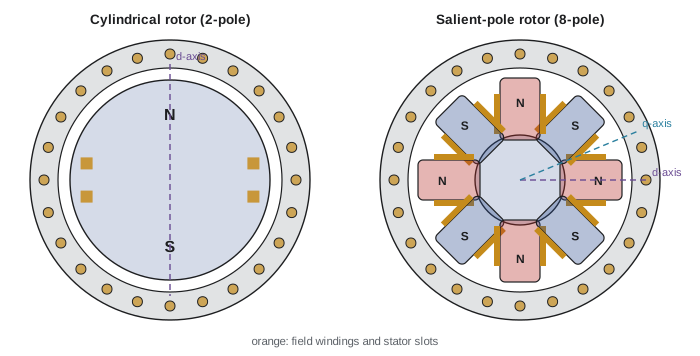
- Cylindrical (round) rotors, with the field winding in slots of a solid steel forging, for high speeds: 2-pole (3600 rpm at 60 Hz) and 4-pole (1800 rpm) turbine generators driven by steam and gas turbines. Their long, narrow shape limits centrifugal stresses.
- Salient-pole rotors, with many projecting poles, for low speeds: hydro generators with 20 to over 80 poles turning at 100 to 360 rpm, and many motors. Their air gap varies around the rotor, so they have different reactances along and across the poles (direct and quadrature axes).
The field current is supplied by an exciter: traditionally a DC generator, now usually a brushless exciter (a small AC generator on the same shaft with rotating rectifiers) or a static exciter (a controlled rectifier feeding the field through slip rings). An automatic voltage regulator (AVR) adjusts the field current to control terminal voltage and reactive power.
Worked problem
Speed and poles
A hydro generator must produce 60 Hz at 144 rpm. How many poles does it need? How many for a gas turbine generator at 3600 rpm?
Show solution
- \(p = 120 f/n = 120 \times 60/144 = 50\) poles.
- At 3600 rpm: \(p = 120 \times 60/3600 = 2\) poles.
Answer: 50 poles for the hydro unit and 2 for the turbine generator. The hydro generator's many poles give it a large diameter and short axial length; the turbine generator is long and slender.
EMF and the phasor model
The EMF induced per phase follows the transformer EMF equation (Lesson 1), with a winding factor \(k_w\) (typically 0.9 to 0.96) accounting for the distribution of coils in slots (Lesson 6):
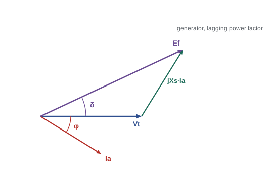
With the machine loaded, armature current produces its own rotating mmf, which combines with the field mmf (armature reaction). For a cylindrical rotor, armature reaction and leakage together are represented by a single synchronous reactance \(X_s\), typically 1.0 to 2.0 per unit for turbine generators. Armature resistance is small (under 0.01 pu) and usually neglected. The per-phase model is then a voltage source \(E_f\) behind \(X_s\):
The angle \(\delta\) by which \(\mathbf{E}_f\) leads \(\mathbf{V}_t\) is the power angle (or load angle). It corresponds physically to the angle between the rotor's field axis and the resultant air-gap field.
Power-angle relationship and stability
For a generator connected to a large system, neglecting resistance, the real power delivered and the reactive power are:
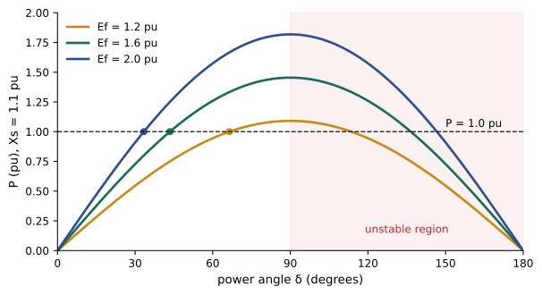
(per phase, or without the factor 3 in per unit). Real power depends on the power angle, which the prime mover controls: opening the turbine valve accelerates the rotor slightly, advancing \(\delta\) until electrical output matches mechanical input. Reactive power depends mainly on the excitation: an overexcited machine (\(E_f\cos\delta > V_t\)) supplies reactive power to the grid, behaving like a capacitor; an underexcited machine absorbs it.
Power is greatest at \(\delta = 90°\): the steady-state stability limit \(P_{max} = 3E_fV_t/X_s\). Beyond it, extra mechanical input cannot be converted, the rotor accelerates away from synchronism, and the machine "pole slips", with violent current and torque pulsations; protection must trip it. In practice generators operate with \(\delta\) well below 90° to leave margin for disturbances (transient stability, ELE-380), typically 20° to 40° at full load.
import numpy as np

# cylindrical-rotor synchronous generator on an infinite bus, per unit
V, Xs = 1.0, 1.1                       # terminal voltage and synchronous reactance (Ra neglected)
print(" P     pf            E (pu)  delta (deg)  Pmax (pu)")
for P, pf, kind in ((1.0, 0.85, "lagging"), (1.0, 1.0, "unity"), (1.0, 0.95, "leading")):
    phi = np.arccos(pf) * (1 if kind == "lagging" else -1)
    I = P / (V * pf) * np.exp(-1j * phi)            # current phasor (lagging = negative angle)
    E = V + 1j * Xs * I
    print(f"{P:4.1f}  {pf:.2f} {kind:8s}  {abs(E):6.3f}   {np.degrees(np.angle(E)):8.1f}    {abs(E) * V / Xs:6.3f}")

# V-curves: armature current versus excitation for constant real power
print("V-curve points (P = 0.5 pu):")
P = 0.5
for E in (0.9, 1.0, 1.1, 1.2, 1.4, 1.6, 1.8):
    s = P * Xs / (E * V)
    if s > 1:
        print(f"   E = {E:.1f}: cannot deliver P (beyond stability limit)")
        continue
    d = np.arcsin(s)
    I = (E * np.exp(1j * d) - V) / (1j * Xs)
    Q = (V * np.conj(I)).imag
    tag = "overexcited, supplies vars" if Q > 0 else "underexcited, absorbs vars"
print(f" E = {E:.1f}: delta {np.degrees(d):5.1f} deg, |I| = {abs(I):.3f} pu, Q = {Q:+.3f} pu ({tag})")P pf E (pu) delta (deg) Pmax (pu) 1.0 0.85 lagging 2.010 33.2 1.827 1.0 1.00 unity 1.487 47.7 1.351 1.0 0.95 leading 1.272 59.9 1.156 V-curve points (P = 0.5 pu): E = 0.9: delta 37.7 deg, |I| = 0.564 pu, Q = -0.261 pu (underexcited, absorbs vars) E = 1.0: delta 33.4 deg, |I| = 0.522 pu, Q = -0.150 pu (underexcited, absorbs vars) E = 1.1: delta 30.0 deg, |I| = 0.502 pu, Q = -0.043 pu (underexcited, absorbs vars) E = 1.2: delta 27.3 deg, |I| = 0.504 pu, Q = +0.060 pu (overexcited, supplies vars) E = 1.4: delta 23.1 deg, |I| = 0.564 pu, Q = +0.261 pu (overexcited, supplies vars) E = 1.6: delta 20.1 deg, |I| = 0.677 pu, Q = +0.457 pu (overexcited, supplies vars) E = 1.8: delta 17.8 deg, |I| = 0.819 pu, Q = +0.649 pu (overexcited, supplies vars)
At rated output (1.0 pu real power), the generator needs an internal EMF of 2.01 pu at 0.85 power factor lagging, 1.49 pu at unity and 1.27 pu at 0.95 leading. The weaker the excitation, the larger the power angle and the smaller the stability margin: at 0.95 leading, \(\delta\) is 60° and the pull-out power is only 1.16 pu, while at 0.85 lagging \(\delta\) is 33° with pull-out power of 1.83 pu. This is why underexcited operation, absorbing reactive power, is limited by stability as well as by heating.
Worked problem
Power angle
A generator with \(X_s = 1.2\) pu has \(E_f = 1.6\) pu and is connected to an infinite bus at 1.0 pu. Find the power angle when it delivers 0.8 pu, and its reactive power output.
Show solution
- \(\sin\delta = PX_s/(E_fV) = 0.8 \times 1.2/1.6 = 0.6\); \(\delta = 36.9°\).
- \(Q = (V/X_s)(E_f\cos\delta - V) = (1/1.2)(1.6 \times 0.8 - 1) = 0.233\) pu.
Answer: The power angle is 36.9°, and the machine supplies 0.23 pu of reactive power (overexcited). Its pull-out power at this excitation is \(1.6/1.2 = 1.33\) pu.
Excitation control and V-curves
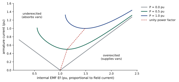
Holding real power constant and varying field current traces out a V-curve: armature current is minimum at unity power factor, rising on either side as the machine supplies (overexcited) or absorbs (underexcited) reactive power. The code's V-curve at 0.5 pu shows current falling from 0.56 pu at \(E_f = 0.9\) to a minimum near 0.50 pu around \(E_f = 1.14\) (unity power factor), then rising to 0.82 pu at \(E_f = 1.8\) as the machine supplies 0.65 pu of reactive power. A family of V-curves at different real power levels is a standard characteristic of synchronous machines.
Generators therefore provide two essential services: real power (controlled by the prime mover and governor) and voltage support through reactive power (controlled by excitation and the AVR). A synchronous condenser is a synchronous motor running with no mechanical load, used only to supply or absorb reactive power and to add inertia and short-circuit strength to the grid. As synchronous generators are replaced by inverter-based wind, solar and batteries, synchronous condensers have been installed in several grids to replace these lost services.
Connecting to the grid
Before a generator's breaker is closed onto a live system, its voltage must match the grid in four respects:
- Magnitude: terminal voltage equal to bus voltage (adjusted by the field).
- Frequency: slightly above grid frequency, so the machine picks up a little load rather than motoring (adjusted by the governor).
- Phase angle: in phase at the moment of closing, typically within about 10°.
- Phase sequence: the same rotation, checked once at commissioning.
Synchronizing relays (synch-check) and automatic synchronizers supervise these conditions. Closing out of phase produces huge currents and torques that can damage the shaft, couplings and windings. The same principles apply to standby generators paralleling with each other or with the utility in data centres (DCE-340).
Once connected, the generator's speed is locked to the grid. Its governor shares load changes with other units according to its droop setting (typically 4 to 5%: frequency falling 5% would raise output from zero to full), so that many generators share frequency regulation stably (ELE-380).
Worked problem
Synchronizing error
A generator is closed onto a 1.0 pu bus with its own voltage at 1.0 pu but 20° out of phase. With a combined reactance (machine transient reactance plus transformer) of 0.3 pu, estimate the initial current.
Show solution
- Voltage difference magnitude: \(2 \times 1.0 \times \sin(10°) = 0.347\) pu.
- Current \(\approx 0.347/0.3 = 1.16\) pu.
Answer: More than full-load current flows instantly, with a corresponding torque shock to the shaft. At 120° out of phase, the voltage difference would be 1.73 pu and the current nearly six times rated, which is why synch-check relays block closing outside a narrow window.
The capability curve
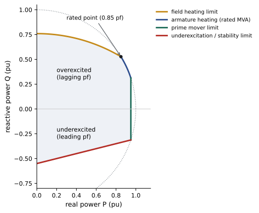
A generator's permissible operating region in the P-Q plane is bounded by several limits:
- Armature heating: a circle of radius equal to rated MVA.
- Field heating: limits overexcited operation (high reactive output at lagging power factor).
- Prime mover: limits real power.
- Underexcitation: stator end-core heating and steady-state stability limit leading operation.
Operators and system planners use the capability curve to know how much reactive power each unit can provide, which matters during heat waves and contingencies when voltage support is scarce. Grid codes require generators to provide reactive power across a specified power factor range, typically 0.90 lagging to 0.95 leading at the terminals.
Synchronous motors
A synchronous machine runs as a motor when electrical power flows in: the rotor lags the stator field by the power angle (\(\mathbf{V}_t = \mathbf{E}_f + jX_s\mathbf{I}_a\)), and it runs at exactly synchronous speed regardless of load up to the pull-out torque. A synchronous motor has no starting torque of its own at line frequency, because the rotating field passes the rotor too fast for it to lock in. Large synchronous motors therefore start as induction motors using damper (amortisseur) windings in the pole faces, then apply field current near synchronous speed to pull into step, or they are started by a variable-frequency drive. Damper windings also damp oscillations of the power angle.
Synchronous motors are chosen for large, constant-speed loads such as compressors, refiners and mills, where their high efficiency and ability to operate at leading power factor (correcting the plant's power factor) justify their cost and complexity.
Worked problem
Power factor correction with a synchronous motor
A plant draws 4000 kW at 0.75 lagging power factor. A new 1000 kW synchronous motor is to be run overexcited so the plant's overall power factor becomes 0.95 lagging. What reactive power must the motor supply, and what is its kVA rating and power factor?
Show solution
- Existing Q: \(4000 \times \tan(\cos^{-1}0.75) = 4000 \times 0.882 = 3528\) kvar.
- New total P: 5000 kW; allowed Q at 0.95: \(5000 \times 0.329 = 1643\) kvar.
- Motor must supply \(3528 - 1643 = 1885\) kvar (leading).
- Motor kVA \(= \sqrt{1000^2 + 1885^2} = 2134\) kVA; power factor \(= 1000/2134 = 0.47\) leading.
Answer: The motor must supply about 1.9 Mvar, requiring a 2.1 MVA rating at 0.47 leading power factor, twice its mechanical rating. In practice, a motor rated 0.8 or 0.9 leading supplies part of the correction, with capacitors (ELEC-210) providing the rest.
Permanent magnet synchronous motors
Replacing the rotor's field winding with permanent magnets gives the permanent magnet synchronous motor (PMSM). With no field current and almost no rotor losses, PMSMs reach efficiencies of 95 to 97% even in small sizes and have high power density, so they are used in electric vehicles, high-efficiency HVAC compressors and fans, servo drives, wind turbines and data centre cooling equipment. They require an inverter that knows the rotor position, and their flux cannot be reduced directly, so operation above base speed uses field weakening by injecting stator current that opposes the magnet flux, which must be managed to avoid demagnetizing the magnets or producing dangerous overvoltages if the inverter trips at high speed. Interior PM designs add reluctance torque from rotor saliency, and synchronous reluctance motors use saliency alone, avoiding rare-earth magnets.
Lesson 10 extends this model to salient poles, short-circuit transients and transient stability, and Lesson 11 covers permanent magnet machines in more depth.
Common mistakes
MistakeOperating a generator close to δ = 90°.
InsteadLeave stability margin; the steady-state limit is reached at 90°, and disturbances need more.
MistakeAssuming excitation controls real power.
InsteadReal power is set by the prime mover; excitation mainly controls reactive power and voltage.
MistakeClosing a generator breaker without synchronizing.
InsteadMatch voltage, frequency, phase angle and sequence; use synch-check relays.
MistakeRunning a generator deeply underexcited to absorb vars without checking limits.
InsteadUnderexcitation reduces the stability margin and heats the stator core ends.
MistakeExpecting a synchronous motor to start without help.
InsteadStart it with damper windings, a pony motor or a VFD.
Summary and key terms
- Synchronous machines have a three-phase stator and a DC or permanent magnet field rotor; f = pn/120.
- Cylindrical rotors suit high-speed turbine generators; salient poles suit low-speed hydro and motors.
- The per-phase model is Ef behind synchronous reactance Xs; δ is the power angle.
- P = (EfVt/Xs) sin δ; the steady-state limit is at δ = 90°.
- Excitation controls reactive power: overexcited machines supply vars, underexcited absorb them.
- V-curves show armature current versus field current, minimum at unity power factor.
- Synchronizing requires matched voltage, frequency, phase and sequence; capability curves bound operation.
- Synchronous motors run at exact synchronous speed and can correct power factor; PMSMs offer very high efficiency.
- Synchronous reactance
- The reactance representing armature reaction and leakage in the steady-state model.
- Power angle
- The angle between the internal EMF and terminal voltage.
- Excitation
- The field current supplied to the rotor.
- Automatic voltage regulator
- A controller adjusting excitation to hold voltage or reactive power.
- Overexcited
- Operation supplying reactive power, with Ef cos δ > Vt.
- V-curve
- Armature current versus field current at constant real power.
- Synchronous condenser
- An unloaded synchronous machine used for reactive power and inertia.
- Pole slipping
- Loss of synchronism when the power angle exceeds the stability limit.
- Capability curve
- The permissible P-Q operating region of a generator.
- Damper winding
- A cage winding in the pole faces used for starting and damping.
- PMSM
- Permanent magnet synchronous motor.
Practice problems
Work each problem on paper first, then reveal the answer to check.
Speed of a 12-pole, 60 Hz synchronous machine?
Show answer
600 rpm.
Ef = 1.5 pu, V = 1.0 pu, Xs = 1.0 pu. Maximum power?
Show answer
1.5 pu.
Same machine delivers 0.75 pu. Power angle?
Show answer
sin δ = 0.5, δ = 30°.
Reactive power in that case?
Show answer
1.5 cos 30° − 1 = 0.299 pu supplied.
What controls a grid-connected generator's real power and its reactive power?
Show answer
Real power by the prime mover (governor); reactive power by excitation (AVR).
At what power factor is armature current minimum on a V-curve?
Show answer
Unity.
List the four synchronizing conditions.
Show answer
Voltage magnitude, frequency, phase angle and phase sequence.
A generator with 5% droop: frequency falls 1%. Change in output?
Show answer
20% of rating (1/5).
Why can't a synchronous motor start on its own at line frequency?
Show answer
The field rotates too fast relative to the stationary rotor to lock in; average torque is zero.
Name two applications of PMSMs.
Show answer
Electric vehicles, HVAC compressors and fans, servo drives, wind turbines.
Lesson quiz · 5 questions
Score 60% or more to complete this lesson.
Create a free account to save your progress, take quizzes and earn a certificate.