
ELE-370 · Lesson 1 of 12 · 32 min
Magnetic circuits
Almost every electric machine converts energy through a magnetic field. Transformers transfer energy between circuits through a shared magnetic flux; motors and generators convert between electrical and mechanical energy as conductors and magnetic fields interact. Electric machines consume roughly 45% of the world's electricity through motors alone, and every kilowatt-hour from a generator passes through several transformers on its way to a load. Designing, selecting and operating these machines starts with magnetic circuits: how current in a coil produces magnetic flux in an iron core, how much current is needed, where energy is lost, and how voltages and forces arise. This lesson builds those foundations; the section at the end of this lesson shows how the twelve lessons apply them to every major type of machine.
Magnetic quantities
A current-carrying conductor produces a magnetic field. Four quantities describe it:
- Magnetic field intensity \(H\) (A/m): the "magnetizing force" produced by currents.
- Magnetic flux density \(B\) (tesla, T = Wb/m²): the field's effect on materials and moving charges.
- Magnetic flux \(\Phi\) (weber, Wb): the total flux through an area, \(\Phi = BA\) for uniform \(B\) perpendicular to area \(A\).
- Magnetomotive force (mmf) \(\mathcal{F} = Ni\) (ampere-turns, A-t): the driving force of a coil of \(N\) turns carrying current \(i\).
In a material, \(B\) and \(H\) are related by the permeability \(\mu\):
Air and non-magnetic materials have \(\mu_r \approx 1\). Ferromagnetic materials such as electrical steel have relative permeabilities of several thousand at moderate flux densities, which is why machines use iron cores: a given current produces far more flux in iron than in air.
Ampère's circuital law relates the field to the current enclosed by a closed path:
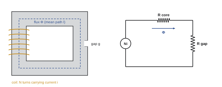
For a core of uniform cross-section with mean path length \(l\), this gives \(Hl = Ni\).
The magnetic circuit
Combining \(Hl = Ni\), \(B = \mu H\) and \(\Phi = BA\) gives:
This is the magnetic equivalent of Ohm's law: mmf plays the role of voltage, flux the role of current, and reluctance \(\mathcal{R}\) (A-t/Wb) the role of resistance. Reluctances in series add, and in parallel combine like parallel resistances, so magnetic structures can be analyzed as circuits. The analogy has limits: iron's permeability changes with flux density, some flux leaks through the air around the core, and flux spreads out (fringes) at air gaps, increasing the gap's effective area.
| Electric circuit | Magnetic circuit |
|---|---|
| Electromotive force \(V\) (V) | Magnetomotive force \(\mathcal{F} = Ni\) (A-t) |
| Current \(I\) (A) | Flux \(\Phi\) (Wb) |
| Resistance \(R = l/(\sigma A)\) | Reluctance \(\mathcal{R} = l/(\mu A)\) |
| Conductivity \(\sigma\) | Permeability \(\mu\) |
| \(V = IR\) | \(\mathcal{F} = \Phi\mathcal{R}\) |
Worked problem
Reluctance of a core with an air gap
A core has a mean path length of 0.60 m, a cross-section of 16 cm², relative permeability 3000, and a 1.0 mm air gap. A 400-turn coil must produce a flux density of 1.0 T. Find the reluctances and the current, ignoring fringing.
Show solution
- Core: \(\mathcal{R}_c = 0.60/(3000 \times 4\pi \times 10^{-7} \times 0.0016) = 99{,}500\) A-t/Wb.
- Gap: \(\mathcal{R}_g = 0.001/(4\pi \times 10^{-7} \times 0.0016) = 497{,}000\) A-t/Wb.
- Flux: \(\Phi = 1.0 \times 0.0016 = 1.6\) mWb. mmf \(= 1.6 \times 10^{-3} \times 596{,}500 = 954\) A-t.
- Current: \(954/400 = 2.39\) A.
Answer: The 1 mm gap has five times the reluctance of the 600 mm of iron, and needs 83% of the mmf. Air gaps dominate magnetic circuits, which is why motors are built with the smallest air gap mechanically practical, while some inductors deliberately include a gap to make inductance stable and avoid saturation.
Saturation and the B-H curve
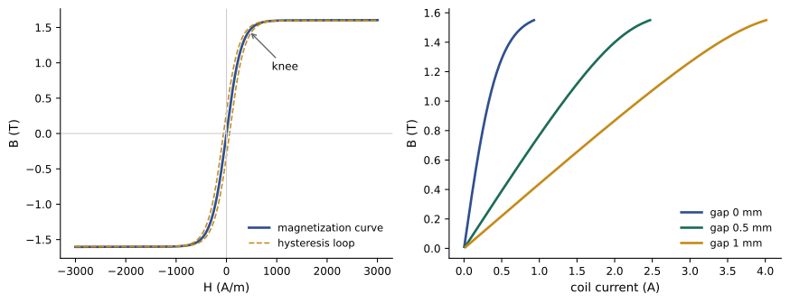
Real ferromagnetic materials are not linear. As \(H\) increases, \(B\) rises steeply at first, then the curve bends over (the "knee") and flattens as the material saturates, typically at 1.5 to 2.0 T for electrical steels. Beyond saturation, extra current produces little extra flux. Machines are designed to operate near the knee, using the iron efficiently without demanding excessive magnetizing current.
With a nonlinear core, the circuit can no longer be solved with a fixed reluctance. Instead, for a required flux density, the core's \(H\) is read from the B-H curve, and the mmf is the sum of \(H_c l_c\) for the core and \(B g/\mu_0\) for the gap.
import numpy as np
from scipy.optimize import brentq

mu0 = 4e-7 * np.pi
# core: silicon steel modelled with a saturating B-H curve  B = Bs * tanh(H / H0) + mu0 * H
Bs, H0 = 1.6, 300.0
def H_of_B(B):
    return brentq(lambda H: Bs * np.tanh(H / H0) + mu0 * H - B, 0, 1e7)

l_core, A, N = 0.60, 0.0016, 400        # mean core path (m), area (m2), turns
for gap_mm in (0.0, 0.5, 1.0):
    g = gap_mm / 1000
    print(f"air gap {gap_mm} mm:")
    for B in (0.8, 1.2, 1.5):
        Hc = H_of_B(B)
        F_core = Hc * l_core
        F_gap = B / mu0 * g
        I = (F_core + F_gap) / N
        print(f"   B = {B} T: core {F_core:7.0f} A-t, gap {F_gap:6.0f} A-t, current {I:6.2f} A,"
f" L = {N * B * A / I:5.2f} H")air gap 0.0 mm: B = 0.8 T: core 99 A-t, gap 0 A-t, current 0.25 A, L = 2.07 H B = 1.2 T: core 175 A-t, gap 0 A-t, current 0.44 A, L = 1.76 H B = 1.5 T: core 308 A-t, gap 0 A-t, current 0.77 A, L = 1.24 H air gap 0.5 mm: B = 0.8 T: core 99 A-t, gap 318 A-t, current 1.04 A, L = 0.49 H B = 1.2 T: core 175 A-t, gap 477 A-t, current 1.63 A, L = 0.47 H B = 1.5 T: core 308 A-t, gap 597 A-t, current 2.26 A, L = 0.42 H air gap 1.0 mm: B = 0.8 T: core 99 A-t, gap 637 A-t, current 1.84 A, L = 0.28 H B = 1.2 T: core 175 A-t, gap 955 A-t, current 2.82 A, L = 0.27 H B = 1.5 T: core 308 A-t, gap 1194 A-t, current 3.76 A, L = 0.26 H
Without a gap, raising the flux density from 1.2 to 1.5 T requires 75% more current, and the inductance \(L = N\Phi/i\) falls from 1.76 H to 1.24 H as the core saturates. Adding a gap increases the current needed several-fold, but because the gap's reluctance is constant, the total becomes much more linear: the inductance changes much less with current. This is the trade-off used in designing inductors and in understanding why motors draw significant magnetizing current.
Faraday's law and inductance
A changing flux linking a coil induces a voltage (Faraday's law), with a polarity that opposes the change (Lenz's law):
where \(\lambda = N\Phi\) is the flux linkage. For a linear magnetic circuit, inductance is flux linkage per unit current:
Inductance grows with the square of the turns and falls with reluctance, so a gap reduces it. For sinusoidal flux \(\Phi = \Phi_{max}\sin\omega t\), the induced rms voltage is the transformer EMF equation:
This equation is central to machine design: for a given voltage and frequency, it fixes the product \(N\Phi_{max}\). Running a transformer or motor at lower frequency without lowering voltage raises the flux and drives the core into saturation, which is why variable-frequency drives keep the ratio V/f roughly constant (Lesson 7).
Worked problem
Turns for a transformer winding
A transformer core has a cross-section of 100 cm² and is designed for a peak flux density of 1.5 T. How many turns are needed for a 2400 V, 60 Hz winding? What happens if it is connected to 2400 V at 50 Hz?
Show solution
- \(\Phi_{max} = 1.5 \times 0.01 = 0.015\) Wb.
- \(N = 2400/(4.44 \times 60 \times 0.015) = 600\) turns.
- At 50 Hz: \(\Phi_{max} = 2400/(4.44 \times 50 \times 600) = 0.018\) Wb, so \(B_{max} = 1.8\) T.
Answer: 600 turns. At 50 Hz the peak flux density rises 20% to 1.8 T, well into saturation, so the magnetizing current and core losses rise sharply and the transformer overheats. Equipment rated for 60 Hz must be derated or have its voltage reduced in proportion when used at 50 Hz.
Core losses
Alternating flux causes two kinds of loss in the iron, together called core loss or iron loss:
- Hysteresis loss: each cycle around the B-H loop dissipates energy proportional to the loop's area as magnetic domains realign. It is proportional to frequency and roughly to \(B_{max}^{1.6}\) to \(B_{max}^2\) (Steinmetz).
- Eddy-current loss: the changing flux induces circulating currents in the conductive iron, heating it. It is proportional to the square of frequency, flux density and lamination thickness. Cores are therefore built from thin laminations (0.23 to 0.5 mm) of silicon steel, insulated from each other, or from amorphous metals or ferrites for higher frequencies.
Core loss occurs whenever the machine is energized, regardless of load, so it dominates the losses of lightly loaded transformers. Grain-oriented silicon steel and amorphous cores reduce it; efficiency regulations for distribution transformers have driven their use.
Worked problem
Effect of frequency on core loss
A core at 60 Hz and 1.4 T has 300 W of hysteresis loss and 120 W of eddy-current loss. Estimate the losses when the same core operates at 50 Hz with the same peak flux density (the voltage reduced in proportion).
Show solution
- Hysteresis scales with \(f\): \(300 \times 50/60 = 250\) W.
- Eddy current scales with \(f^2\): \(120 \times (50/60)^2 = 83\) W.
- Total: 333 W, down from 420 W.
Answer: About 333 W. Separating the two components this way, from tests at two frequencies, lets designers judge whether thinner laminations (reducing eddy loss) or better steel (reducing hysteresis) would pay off.
Energy and force
A magnetic field stores energy. In a linear system, the stored energy is \(W = \tfrac12 L i^2\), and the energy density in a region with flux density \(B\) is \(B^2/(2\mu)\). Because \(\mu_0\) is thousands of times smaller than iron's permeability, most stored energy sits in the air gaps. Forces arise as the system moves to reduce reluctance: an iron armature is pulled to close a gap, which is the principle of relays, contactors, solenoids and reluctance motors. The force across a gap of area \(A\) is:
Machines convert energy through the same mechanism: the coupling field stores energy, and electrical energy in minus mechanical energy out equals the change in stored field energy. Lesson 2 develops this energy balance into general expressions for force and torque, and the later lessons apply it to each type of machine.
Worked problem
Force of an electromagnet
A contactor's armature faces two pole faces of 4 cm² each, and the gap flux density is 0.8 T. What is the holding force?
Show solution
- Per pole face: \(F = (0.8^2 \times 0.0004)/(2 \times 4\pi \times 10^{-7}) = 102\) N.
- Two faces: 204 N.
Answer: About 200 N, about the weight of a 20 kg mass. Because force scales with \(B^2\), doubling the flux density would quadruple it, which is why magnetic actuators are designed close to saturation.
Permanent magnets
Permanent magnets retain magnetization after the magnetizing field is removed. Their key properties are remanence \(B_r\) (flux density with no applied field) and coercivity \(H_c\) (field needed to demagnetize them). Neodymium-iron-boron magnets have \(B_r\) of about 1.2 to 1.4 T and very high coercivity, enabling the compact, efficient permanent magnet motors used in electric vehicles, wind turbines and appliances. Their drawbacks are cost, reliance on rare-earth supply chains, loss of performance at high temperature, and the risk of irreversible demagnetization by fault currents. Ferrite magnets are cheaper but weaker.
How this course is organized
The twelve lessons move from magnetic fundamentals through each family of machines to practice:
- Lesson 1 (this lesson): magnetic circuits, saturation, Faraday's law, inductance, core losses and permanent magnets.
- Lesson 2: electromechanical energy conversion: energy, co-energy, force, torque and machine sizing.
- Lesson 3: transformers: equivalent circuit, tests, regulation, efficiency and three-phase connections.
- Lesson 4: power transformers in service: vector groups, parallel operation, tap changers, harmonics, thermal loading and condition assessment.
- Lesson 5: DC machines: EMF and torque equations, generators, motors, starting and speed control.
- Lesson 6: AC windings and the rotating magnetic field.
- Lesson 7: induction motors: equivalent circuit, torque-speed curve, starting, drives and efficiency.
- Lesson 8: induction machine dynamics, vector control, braking and induction generators.
- Lesson 9: synchronous machines: phasor model, power angle, excitation, synchronizing and capability.
- Lesson 10: synchronous machine transients, salient poles and stability.
- Lesson 11: permanent magnet, reluctance, stepper and single-phase machines.
- Lesson 12: ratings, testing, condition monitoring, protection and specifying a motor system.
Common mistakes
MistakeIgnoring the air gap because it is short.
InsteadGap reluctance often dominates; a millimetre of air can outweigh a metre of iron.
MistakeUsing a constant permeability above the knee of the B-H curve.
InsteadRead H from the B-H curve and solve the nonlinear circuit.
MistakeRunning 60 Hz equipment at 50 Hz with full voltage.
InsteadFlux rises 20%; reduce voltage in proportion or derate.
MistakeAssuming core loss falls with load.
InsteadCore loss depends on voltage and frequency and is present whenever the machine is energized.
MistakeForgetting fringing at large gaps.
InsteadFringing increases the effective gap area; add about the gap length to each cross-section dimension as a first estimate.
Summary and key terms
- H, B, Φ and mmf describe magnetic fields; B = μH and Φ = BA.
- Ampère's law gives Hl = Ni; reluctance l/(μA) makes Φ = F/R, like Ohm's law.
- Air gaps dominate reluctance; they linearize circuits at the cost of more current.
- Ferromagnetic materials saturate at 1.5–2 T, so the B-H curve must be used near the knee.
- Faraday's law gives e = N dΦ/dt; L = N²/R; E = 4.44 f N Φmax fixes flux for given voltage and frequency.
- Core loss combines hysteresis (∝ f) and eddy current (∝ f² and lamination thickness squared).
- Stored energy concentrates in gaps; gap force is B²A/(2μ0).
- Permanent magnets are characterized by remanence and coercivity; NdFeB enables compact machines.
- Magnetomotive force
- The magnetic driving force of a coil, Ni ampere-turns.
- Reluctance
- Opposition to magnetic flux, l/(μA).
- Permeability
- The ratio of B to H in a material.
- Saturation
- The region where additional H produces little additional B.
- Flux linkage
- The product of turns and the flux they enclose, NΦ.
- Inductance
- Flux linkage per unit current.
- Hysteresis loss
- Energy lost each cycle as a material is magnetized back and forth.
- Eddy current
- Circulating current induced in a conductor by changing flux.
- Lamination
- A thin insulated sheet of core steel that limits eddy currents.
- Fringing
- Spreading of flux at an air gap.
- Remanence
- The flux density a permanent magnet retains with no applied field.
- Coercivity
- The field needed to demagnetize a magnetic material.
Practice problems
Work each problem on paper first, then reveal the answer to check.
A 200-turn coil carries 3 A. What is the mmf?
Show answer
600 A-t.
Reluctance of a 2 mm air gap with area 25 cm²?
Show answer
0.002/(4π × 10⁻⁷ × 0.0025) = 637,000 A-t/Wb.
A coil of 500 turns on a circuit of reluctance 250,000 A-t/Wb. Inductance?
Show answer
500²/250,000 = 1.0 H.
Why does a gapped inductor have more stable inductance?
Show answer
The gap's constant reluctance dominates the total, so changes in iron permeability matter less.
Rms voltage induced in 300 turns by a 60 Hz flux of peak 4 mWb?
Show answer
4.44 × 60 × 300 × 0.004 = 320 V.
A transformer rated 480 V, 60 Hz is used at 50 Hz. What voltage keeps the flux unchanged?
Show answer
480 × 50/60 = 400 V.
Why are cores laminated?
Show answer
Thin insulated sheets limit eddy-current paths, reducing eddy loss, which scales with thickness squared.
Eddy loss is 200 W. Lamination thickness is halved. New eddy loss?
Show answer
50 W.
Force across a 10 cm² gap at 1.2 T?
Show answer
1.44 × 0.001/(2 × 4π × 10⁻⁷) = 573 N.
Give two drawbacks of NdFeB magnets.
Show answer
Cost and rare-earth supply, temperature sensitivity, risk of demagnetization.
Lesson quiz · 5 questions
Score 60% or more to complete this lesson.
Create a free account to save your progress, take quizzes and earn a certificate.