
ELE-370 · Lesson 6 of 12 · 29 min
AC windings and the rotating magnetic field
Induction and synchronous machines, which together convert most of the world's electrical energy, share the same stator: a laminated steel cylinder with slots holding a three-phase winding. When balanced three-phase currents flow in that winding, they produce a magnetic field of constant strength that rotates smoothly around the air gap, without any moving parts. This rotating field is the foundation for Lessons 7 to 11. This lesson explains how AC windings are arranged in slots, why the field rotates and at what speed, how the distribution and pitch of the coils shape the field and the induced voltage, why harmonics arise and how winding design suppresses them, and what happens when the supply is unbalanced or a phase is lost.
Poles, electrical degrees and synchronous speed
A machine with \(p\) poles has \(p/2\) pairs of north and south poles around the air gap. One pole pair corresponds to one full cycle of the field pattern, so it is convenient to measure positions in electrical degrees:
In a 4-pole machine, one mechanical revolution is 720 electrical degrees. A field that advances 360 electrical degrees each cycle of the supply turns \(2/p\) of a revolution per cycle, so its speed, the synchronous speed, is
| Poles | Synchronous speed at 60 Hz | Synchronous speed at 50 Hz | Typical use |
|---|---|---|---|
| 2 | 3,600 rpm | 3,000 rpm | pumps, compressors, steam turbine generators |
| 4 | 1,800 rpm | 1,500 rpm | most general-purpose motors |
| 6 | 1,200 rpm | 1,000 rpm | fans, conveyors |
| 8 | 900 rpm | 750 rpm | large slow loads, crushers |
| 24 to 80 | 300 to 90 rpm | 250 to 75 rpm | hydroelectric generators |
Distributed windings
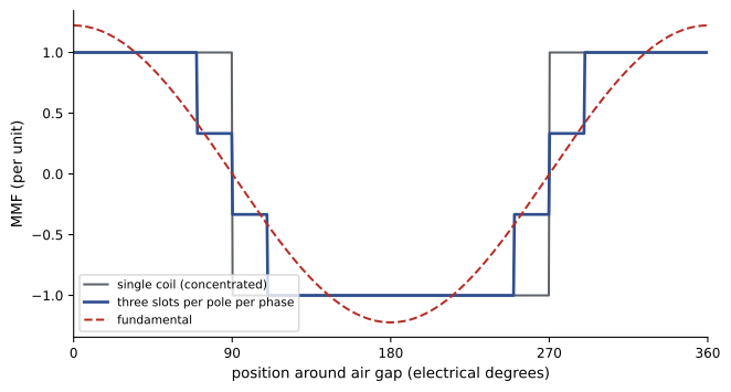
If each phase had a single coil, the air-gap flux density produced by it would be a rectangular wave, rich in harmonics. Practical AC windings instead spread each phase over several slots under each pole. The number of slots per pole per phase is
where \(S\) is the number of slots and \(m\) the number of phases. A 36-slot, 4-pole, three-phase stator has \(q = 3\). Adjacent slots are separated by the slot angle \(\gamma = 180° \times p/S\) electrical, here 20°. The MMF of the coils in adjacent slots is shifted by \(\gamma\), so the step-shaped MMF of each phase approximates a sine wave much better than a single coil would. The cost is that the EMFs of the coils in a group are not quite in phase, so their phasor sum is slightly less than their arithmetic sum. The ratio is the distribution factor:
For \(q = 3\) and \(\gamma = 20°\), \(k_d = \sin 30° / (3 \sin 10°) = 0.960\).
Short pitching
A full-pitch coil spans exactly one pole pitch, 180 electrical degrees, so its two sides sit under opposite poles and their EMFs add directly. Most windings are short-pitched (chorded): each coil spans less than a pole pitch, typically 5/6 or 7/9 of it. The EMFs of the two coil sides then add with a small phase difference, giving a pitch factor
where \(\rho\) is the coil span as a fraction of the pole pitch. Short pitching reduces the fundamental only slightly but suppresses selected harmonics strongly, and it shortens the end windings, saving copper and reducing leakage. The winding factor combines both effects, \(k_w = k_p k_d\), and the EMF per phase is
where \(N\) is the number of series turns per phase and \(\Phi\) the flux per pole, as in the synchronous machine of Lesson 9.
import numpy as np

# Pitch and distribution factors of a three-phase winding: 4 poles, 36 slots (q = 3 slots per pole per phase)
slots, poles, phases = 36, 4, 3
q = slots // (poles * phases)
gamma = np.pi * poles / slots                 # slot angle in electrical radians (20 degrees)

def k_d(h):
    return np.sin(h * q * gamma / 2) / (q * np.sin(h * gamma / 2))

def k_p(h, pitch):                            # pitch as a fraction of full pitch
    return np.sin(h * pitch * np.pi / 2)

print(f"slot angle {np.degrees(gamma):.0f} electrical degrees, q = {q}")
print("pitch     h=1     h=3     h=5     h=7    (winding factor k_w = k_p k_d)")
for slots_pitch in (9, 8, 7):
    pitch = slots_pitch / 9
    row = "  ".join(f"{abs(k_p(h, pitch) * k_d(h)):.3f}" for h in (1, 3, 5, 7))
    print(f"{slots_pitch}/9    {row}")
# EMF per phase: E = 4.44 f N k_w Phi
f, N, Phi = 60, 96, 0.032
for slots_pitch in (9, 8, 7):
    kw = k_p(1, slots_pitch / 9) * k_d(1)
print(f"pitch {slots_pitch}/9: fundamental EMF = 4.44 x {f} x {N} x {kw:.3f} x {Phi} = {4.44 * f * N * kw * Phi:.0f} V per phase")slot angle 20 electrical degrees, q = 3 pitch h=1 h=3 h=5 h=7 (winding factor k_w = k_p k_d) 9/9 0.960 0.667 0.218 0.177 8/9 0.945 0.577 0.140 0.061 7/9 0.902 0.333 0.038 0.136 pitch 9/9: fundamental EMF = 4.44 x 60 x 96 x 0.960 x 0.032 = 785 V per phase pitch 8/9: fundamental EMF = 4.44 x 60 x 96 x 0.945 x 0.032 = 774 V per phase pitch 7/9: fundamental EMF = 4.44 x 60 x 96 x 0.902 x 0.032 = 738 V per phase
For harmonic \(h\), the factors become \(k_{p,h} = \sin(h\rho\pi/2)\) and \(k_{d,h} = \sin(hq\gamma/2)/(q\sin(h\gamma/2))\). A 7/9 pitch cuts the 5th harmonic winding factor from 0.218 to 0.038 while reducing the fundamental by only 6%; an 8/9 pitch is a compromise that suppresses the 7th. Designers choose the pitch to suppress the harmonics that matter most: the 5th and 7th in motors (they cause torque dips and noise) and, in generators, the harmonics that would distort the voltage waveform. Third harmonics and their multiples cancel in the line-to-line voltages of a wye-connected winding, because they are in phase in all three phases, so they matter less.
Worked problem
Pitch for minimum fifth harmonic
What coil pitch eliminates the 5th harmonic, and what is the fundamental pitch factor? How close can a winding with 6 slots per pole come to it?
Show solution
- The 5th harmonic vanishes when \(\sin(5\rho\pi/2) = 0\), that is, \(5\rho = 4\), so \(\rho = 4/5 = 0.8\).
- Fundamental pitch factor: \(\sin(0.8 \times 90°) = \sin 72° = 0.951\).
- With 6 slots per pole, the possible spans are 6/6, 5/6 and 4/6 of a pole pitch. A 5/6 pitch spans 150° electrical, giving \(k_{p5} = \sin(5 \times 75°) = \sin 375° = 0.259\), \(k_{p7} = |\sin 525°| = 0.259\) and \(k_{p1} = \sin 75° = 0.966\).
Answer: An exact 4/5 pitch eliminates the 5th harmonic at a 4.9% cost in fundamental. With 6 slots per pole, the 5/6 pitch, very common in practice, reduces both the 5th and 7th harmonics to about a quarter while keeping 96.6% of the fundamental.
Why the field rotates
Each phase winding, carrying a sinusoidal current, produces an MMF wave that is sinusoidal in space and fixed in position, but whose amplitude pulsates with the current: phase a produces \(F_a = F_m \cos\omega t \cos\theta\). Such a pulsating wave can be written as the sum of two waves of half the amplitude rotating in opposite directions:
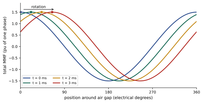
Phases b and c are displaced by 120° in space and their currents by 120° in time. When the three phases are added, the forward-rotating components are all in step and add to \(\tfrac{3}{2} F_m\), while the backward-rotating components are at 0°, 120° and 240° to each other and cancel:
The result is an MMF wave of constant amplitude, one and a half times the peak of one phase, rotating at \(\omega\) electrical radians per second, which is synchronous speed. Swapping any two supply leads reverses the phase sequence and so reverses the direction of rotation, which is how motor direction is changed.
import numpy as np

# Three windings spaced 120 electrical degrees, carrying balanced three-phase currents:
# the total MMF is a wave of constant amplitude 1.5 F_max that rotates at synchronous speed.
theta = np.linspace(0, 2 * np.pi, 3601)        # position around the air gap (electrical radians)
def total_mmf(t, ia_scale=1.0, ib_scale=1.0, ic_scale=1.0):
    w = 2 * np.pi * 60
    F = (ia_scale * np.cos(w * t) * np.cos(theta)
         + ib_scale * np.cos(w * t - 2 * np.pi / 3) * np.cos(theta - 2 * np.pi / 3)
         + ic_scale * np.cos(w * t + 2 * np.pi / 3) * np.cos(theta + 2 * np.pi / 3))
    k = np.argmax(F)
    return F[k], np.degrees(theta[k])

print("balanced currents:")
for ms in (0, 1, 2, 3, 4):
    t = ms / 1000
    peak, where = total_mmf(t)
    print(f"  t = {ms} ms: peak MMF {peak:.3f} (per unit of one phase) at {where:6.1f} electrical degrees")
print(f"  the peak moves {360 * 60 / 1000:.1f} electrical degrees per ms: 360 electrical degrees per cycle")
print("phase c open (single phasing): currents in a and b only, equal and opposite")
for ms in (0, 2, 4, 6, 8):
    t = ms / 1000
    w = 2 * np.pi * 60
    F = np.cos(w * t) * (np.cos(theta) - np.cos(theta - 2 * np.pi / 3))
    k = np.argmax(F)
print(f" t = {ms} ms: peak MMF {F[k]:.3f} at {np.degrees(theta[k]):6.1f} degrees")balanced currents: t = 0 ms: peak MMF 1.500 (per unit of one phase) at 0.0 electrical degrees t = 1 ms: peak MMF 1.500 (per unit of one phase) at 21.6 electrical degrees t = 2 ms: peak MMF 1.500 (per unit of one phase) at 43.2 electrical degrees t = 3 ms: peak MMF 1.500 (per unit of one phase) at 64.8 electrical degrees t = 4 ms: peak MMF 1.500 (per unit of one phase) at 86.4 electrical degrees the peak moves 21.6 electrical degrees per ms: 360 electrical degrees per cycle phase c open (single phasing): currents in a and b only, equal and opposite t = 0 ms: peak MMF 1.732 at 330.0 degrees t = 2 ms: peak MMF 1.263 at 330.0 degrees t = 4 ms: peak MMF 0.109 at 330.0 degrees t = 6 ms: peak MMF 1.104 at 150.0 degrees t = 8 ms: peak MMF 1.718 at 150.0 degrees
Unbalance and single phasing
When the supply voltages are unbalanced, the currents contain a negative-sequence component, which produces a field rotating backward at synchronous speed. For a motor running forward, this backward field induces rotor currents at nearly twice supply frequency and produces a braking torque. Because the motor's impedance to negative sequence is low (similar to its locked-rotor impedance), a small voltage unbalance causes a large current unbalance: typically, each 1% of voltage unbalance causes 6 to 10% current unbalance, and the extra rotor and stator heating rises roughly with twice the square of the percent unbalance. NEMA MG 1 recommends derating motors when voltage unbalance exceeds 1% and not operating them above 5%.
Single phasing, the loss of one supply phase from a blown fuse or broken conductor, is the extreme case. As the code above shows, the remaining two phases carry equal and opposite currents and produce a pulsating field that does not rotate: it is the sum of equal forward and backward fields. A motor that is already running keeps turning, because the forward field dominates at low slip, but draws about 1.7 to 2 times its normal current in the remaining phases and overheats; a stopped motor cannot start and draws locked-rotor current. Overload relays sized correctly will trip, and electronic motor protection relays detect phase loss and unbalance directly (Lesson 12).
Worked problem
Voltage unbalance
Line voltages at a motor are 600, 585 and 612 V. Find the percent unbalance and the approximate derating factor if NEMA MG 1 recommends 0.95 at 2% and 0.88 at 3%.
Show solution
- Average: \((600 + 585 + 612)/3 = 599\) V.
- Maximum deviation: \(599 - 585 = 14\) V.
- Unbalance: \(100 \times 14/599 = 2.3\%\).
Answer: The unbalance is 2.3%, which calls for derating to about 93% of rated load (interpolating), and expect current unbalance of roughly 15 to 25%. The supply should be investigated: unbalanced single-phase loads, an open-delta bank or a failing connection are common causes.
Space harmonics, slotting and their effects
Even with distributed, short-pitched windings, the MMF contains small harmonics of orders \(h = 6k \pm 1\) (5, 7, 11, 13, …) in a three-phase winding. The 5th harmonic field rotates backward at one fifth of synchronous speed and the 7th forward at one seventh. In induction motors these fields produce parasitic torques that can create dips in the torque-speed curve near one seventh of synchronous speed, where a lightly loaded motor may "crawl". Slot openings modulate the air-gap permeance and produce slot harmonics, which cause magnetic noise and, if the numbers of stator and rotor slots are poorly chosen, cogging, in which the motor locks at low speed. Designers avoid these problems by choosing slot combinations carefully and by skewing the rotor bars by about one slot pitch, which averages out the slot harmonics at a small cost in fundamental torque.
Winding construction and connections
Small and medium machines use random-wound coils of round enamelled wire, inserted into slots lined with insulating paper. Large machines and those above about 1 kV use form-wound coils of rectangular insulated conductors, pre-shaped and taped with mica-based insulation that resists partial discharge. Double-layer windings, with two coil sides per slot, allow any pitch and are standard for form-wound machines. Coil groups of each phase are connected in series or in parallel paths to suit the rated voltage, and the phases are connected in wye or delta. Many motors bring out six or nine leads so they can be connected for two voltages (for example, 230 V in delta or parallel wye and 460 V in series wye) or started wye and run in delta (Lesson 7).
Common mistakes
MistakeUsing mechanical degrees in winding factor formulas.
InsteadSlot angle and coil pitch must be in electrical degrees: multiply mechanical by p/2.
MistakeForgetting the winding factor in the EMF equation.
InsteadUse \(E = 4.44 f N k_w \Phi\); \(k_w\) is typically 0.85 to 0.96.
MistakeIgnoring a small voltage unbalance.
InsteadA 2% voltage unbalance can cause 15 to 20% current unbalance and significant heating.
MistakeAssuming a single-phased motor will stop.
InsteadA running motor keeps turning but overheats; it must be protected.
MistakeChoosing full-pitch coils for lowest cost.
InsteadShort pitching suppresses harmonics and shortens end windings.
Summary and key terms
- Synchronous speed is \(120f/p\) rpm; electrical degrees equal mechanical degrees times \(p/2\).
- Distributed windings with q slots per pole per phase approximate a sinusoidal MMF, with distribution factor \(k_d\).
- Short pitching reduces selected harmonics at a small cost in fundamental, with pitch factor \(k_p\).
- EMF per phase is \(4.44 f N k_w \Phi\).
- Balanced three-phase currents produce a constant MMF of 1.5 times one phase's peak, rotating at synchronous speed.
- Unbalance creates a backward field and heating; single phasing produces a pulsating field.
- Space and slot harmonics cause parasitic torques, noise and cogging, reduced by slot choice and skew.
- Electrical degree
- Angle measured so that one pole pair spans 360°.
- Synchronous speed
- The speed of the rotating field, 120f/p rpm.
- Slots per pole per phase
- The number q of slots each phase occupies under each pole.
- Distribution factor
- The reduction in EMF from spreading a phase over several slots.
- Pitch factor
- The reduction in EMF from a coil spanning less than a pole pitch.
- Winding factor
- The product of pitch and distribution factors.
- Rotating magnetic field
- A field of constant amplitude rotating at synchronous speed.
- Negative sequence
- A set of balanced phasors in reverse rotation, producing a backward field.
- Single phasing
- Loss of one phase of a three-phase supply.
- Skew
- Twisting rotor bars along the stack to reduce slot harmonics.
Practice problems
Work each problem on paper first, then reveal the answer to check.
Synchronous speed of a 10-pole machine at 60 Hz?
Show answer
720 rpm.
Slot angle of a 48-slot, 4-pole stator?
Show answer
15 electrical degrees.
q for 48 slots, 4 poles, 3 phases?
Show answer
4.
Distribution factor for q = 4, γ = 15°?
Show answer
\(\sin 30°/(4 \sin 7.5°) = 0.958\).
Pitch factor for a 5/6 pitch?
Show answer
\(\sin 75° = 0.966\).
EMF for f = 60 Hz, N = 120, k_w = 0.92, Φ = 0.02 Wb?
Show answer
\(4.44 \times 60 \times 120 \times 0.92 \times 0.02 = 588\) V.
Amplitude of the rotating MMF relative to one phase?
Show answer
1.5 times.
How is the direction of rotation reversed?
Show answer
Swap any two supply leads.
Unbalance for 480, 470 and 490 V?
Show answer
Average 480; max deviation 10; 2.1%.
Which harmonics remain in a balanced three-phase winding MMF?
Show answer
Orders 6k ± 1: 5, 7, 11, 13, …
Lesson quiz · 5 questions
Score 60% or more to complete this lesson.
Create a free account to save your progress, take quizzes and earn a certificate.