
ELE-370 · Lesson 4 of 12 · 28 min
Power transformers in service
Lesson 3 developed the transformer equivalent circuit and the basic three-phase connections. This lesson follows transformers into service, where engineers must choose vector groups and grounding, run units in parallel, regulate voltage with tap changers, cope with harmonic loads, decide how far a transformer can be overloaded on a hot afternoon, and judge from oil samples and test results whether an ageing unit is safe to keep in service. A large power transformer costs millions of dollars, takes a year or more to replace, and can be the single point of failure for a substation, so these questions have real consequences.
Vector groups and phase displacement
A three-phase transformer's vector group describes its winding connections and the phase displacement between the high-voltage and low-voltage line voltages. In the IEC notation, an upper-case letter gives the high-voltage connection (D for delta, Y for wye, Z for zigzag), a lower-case letter the low-voltage connection, n indicates a brought-out neutral, and a number gives the displacement in 30° steps, read like the hour hand of a clock with the high-voltage phasor at 12 o'clock. Dyn1 means delta primary, grounded wye secondary, with the low-voltage side lagging by 30° (1 o'clock); Dyn11 means it leads by 30°.
| Vector group | Phase shift of LV | Typical use |
|---|---|---|
| Dyn1 (ANSI standard Δ-Y) | lags 30° | North American distribution and commercial step-down |
| Dyn11 | leads 30° | distribution in IEC countries |
| YNd1 or YNd11 | ±30° | generator step-up, delta on the generator side |
| YNyn0 with delta tertiary | 0° | transmission interconnection and autotransformers |
| Dd0 | 0° | industrial supplies, open-delta capability |
| Dzn0 or Yzn11 | 0° or 30° | grounding transformers and rectifier supplies |
North American standards (IEEE C57.12.00 and CSA C88) require the low-voltage side of Δ-Y and Y-Δ units to lag the high-voltage side by 30°, equivalent to Dyn1 or YNd1. Rectifiers for large drives and data centre UPS systems use transformers with several secondaries shifted by different angles, for example 0° and 30° for 12-pulse rectification, so that harmonic currents of the different rectifiers cancel in the primary.
Zero sequence and grounding
Unbalanced loads and ground faults produce zero-sequence currents, which are equal in all three phases and in phase with each other (ELE-380 covers symmetrical components). How a transformer handles them depends on its connections:
- A grounded wye winding allows zero-sequence current to flow in its lines and neutral, but only if the other winding can supply the matching ampere-turns.
- A delta winding traps zero-sequence current: it circulates around the delta but cannot flow in the lines. This lets the delta supply the ampere-turns that balance a grounded wye winding.
- An ungrounded wye blocks zero-sequence current entirely.
So a Dyn transformer gives the secondary a solidly grounded neutral that can carry line-to-neutral loads and ground-fault current, while isolating the primary system from secondary ground faults. A ground fault on the secondary appears on the primary as current in only two lines, which matters for coordinating protection. A Y-Y transformer without a delta tertiary has no path for zero-sequence ampere-turns, so unbalanced line-to-neutral loads shift the neutral and distort voltages; three-limb core designs and delta tertiary windings overcome this. Where a delta-connected system needs a ground reference, for example on the 600 V delta side of a generator or on an ungrounded industrial system that is to be converted, a zigzag or wye-delta grounding transformer provides one.
Parallel operation
Transformers are paralleled to share a large load, to provide redundancy, or to add capacity as load grows. For satisfactory parallel operation they must have:
- The same voltage ratio (within about 0.5%), or circulating current flows even at no load.
- The same phase displacement and polarity; paralleling Dyn1 with Dyn11 produces a 60° difference, effectively a short circuit.
- The same phase sequence.
- Similar per-unit impedances (within about 10%) and similar X/R ratios, so that load divides in proportion to ratings.
Load divides between paralleled transformers in inverse proportion to their ohmic impedances. A transformer with a lower per-unit impedance takes more than its share and may be overloaded while its partner is underloaded.
import numpy as np

# Two transformers in parallel supplying a common load. Impedances in ohms referred to the 600 V side.
V = 600 / np.sqrt(3)                      # per-phase voltage
def z_ohm(z_pu, kva):
    return z_pu * 600 ** 2 / (kva * 1000)

S_load = 2500e3                           # VA, at 0.9 power factor lagging
I_load = S_load / (3 * V) * np.exp(-1j * np.arccos(0.9))

cases = [
    ("identical 1500 kVA units, 5.75%", (1500, 0.0575, 1.0), (1500, 0.0575, 1.0)),
    ("1500 kVA at 5.75% with 1000 kVA at 4.5%", (1500, 0.0575, 1.0), (1000, 0.045, 1.0)),
    ("1500 kVA at 5.75% with 1000 kVA at 7.0%", (1500, 0.0575, 1.0), (1000, 0.070, 1.0)),
]
for name, (s1, z1, t1), (s2, z2, t2) in cases:
    Z1 = z_ohm(z1, s1) * (0.15 + 1j) / abs(0.15 + 1j)          # X/R about 6.7
    Z2 = z_ohm(z2, s2) * (0.15 + 1j) / abs(0.15 + 1j)
    I1 = I_load * Z2 / (Z1 + Z2)
    I2 = I_load * Z1 / (Z1 + Z2)
    l1 = 3 * V * abs(I1) / (s1 * 1000)
    l2 = 3 * V * abs(I2) / (s2 * 1000)
    print(f"{name}: unit 1 at {l1:.0%}, unit 2 at {l2:.0%} of rating (load 2500 kVA, combined rating {s1 + s2} kVA)")

# Tap mismatch: the same identical units, one on a tap 2.5% higher, at no load
Z = z_ohm(0.0575, 1500) * (0.15 + 1j) / abs(0.15 + 1j)
dV = 0.025 * V
I_circ = dV / (2 * Z)
I_rated = 1500e3 / (3 * V)
print(f"2.5% tap mismatch on identical units: circulating current {abs(I_circ):.0f} A = {abs(I_circ) / I_rated:.0%} of rated current, flowing even at no load")identical 1500 kVA units, 5.75%: unit 1 at 83%, unit 2 at 83% of rating (load 2500 kVA, combined rating 3000 kVA) 1500 kVA at 5.75% with 1000 kVA at 4.5%: unit 1 at 90%, unit 2 at 115% of rating (load 2500 kVA, combined rating 2500 kVA) 1500 kVA at 5.75% with 1000 kVA at 7.0%: unit 1 at 108%, unit 2 at 88% of rating (load 2500 kVA, combined rating 2500 kVA) 2.5% tap mismatch on identical units: circulating current 314 A = 22% of rated current, flowing even at no load
With matched per-unit impedances, each unit carries the same fraction of its rating. Pairing the 1500 kVA unit with a 1000 kVA unit of lower impedance overloads the smaller unit to 115% even though the total load equals the combined rating; if the smaller unit has the higher impedance, the larger one is overloaded instead. The usable capacity of the pair is reached when the first unit reaches its rating. A 2.5% difference in tap position, one step on many tap changers, drives a circulating current of over 20% of rated current through both units even at no load, adding losses and heating. Paralleled units with on-load tap changers therefore use master-follower or circulating-current-minimizing control.
Tap changers and voltage control
Taps change the number of turns in use on one winding, usually the high-voltage winding because its current is lower, to adjust the ratio and so the secondary voltage.
- De-energized tap changers (DETC, also called off-circuit or no-load tap changers) are set only with the transformer out of service. Distribution transformers typically have five positions: nominal, ±2.5% and ±5%. They compensate for the long-term supply voltage at the site.
- On-load tap changers (OLTC) switch taps under load, using a diverter switch with transition resistors or reactors so the circuit is never broken and a tap section is never shorted directly. A typical range is ±10% in 32 steps of 0.625%, or 16 steps of 1.25%. An automatic voltage regulator relay raises or lowers the tap to keep the secondary voltage within a bandwidth, with a time delay of 30 to 60 seconds to avoid hunting, and line-drop compensation to regulate the voltage at a point down the feeder.
OLTCs are mechanical devices that operate tens of thousands of times over their life; their contacts wear and the diverter compartment oil degrades from arcing, so they are a leading cause of transformer failures and need regular maintenance. Vacuum-interrupter tap changers greatly reduce contact wear and oil contamination. Step-voltage regulators, autotransformers with OLTCs, perform the same function on distribution feeders (ELE-380).
Harmonics and nonlinear loads
Rectifiers, variable-frequency drives, LED drivers, computer power supplies and electric vehicle chargers draw nonsinusoidal current rich in harmonics. In a transformer, harmonic currents cause extra eddy-current loss in the windings, which rises roughly with the square of the harmonic order, and extra stray loss in structural parts. The K-factor quantifies the effect:
where \(I_h\) is the current at harmonic order \(h\). A transformer serving purely sinusoidal load has \(K = 1\); typical office and data centre loads have K-factors of 4 to 13. K-rated transformers (K-4, K-13, K-20) are designed with conductors and cooling to carry such loads at full rating, while a standard transformer must be derated. Triplen harmonics (3rd, 9th, 15th) from single-phase loads add in the neutral of a wye secondary rather than cancelling, so neutral current can exceed phase current, and they circulate in the delta primary, heating it without appearing in the supply lines.
Worked problem
K-factor of an office load
A feeder's current, in per unit of the fundamental, contains: fundamental 1.0, 3rd 0.6, 5th 0.35, 7th 0.15, 9th 0.08. Find the RMS current and the K-factor.
Show solution
- \(\sum I_h^2 = 1 + 0.36 + 0.1225 + 0.0225 + 0.0064 = 1.511\); RMS \(= \sqrt{1.511} = 1.229\) pu.
- \(\sum I_h^2 h^2 = 1 + 0.36 \times 9 + 0.1225 \times 25 + 0.0225 \times 49 + 0.0064 \times 81 = 1 + 3.24 + 3.06 + 1.10 + 0.52 = 8.92\).
- \(K = 8.92/1.511 = 5.9\).
Answer: The RMS current is 23% above the fundamental and K is about 5.9, so a K-13 rated transformer (or a K-6 if available, or a derated standard unit) is appropriate. Third-harmonic currents of 0.6 pu from each phase add in the neutral to 1.8 pu of the fundamental, so the neutral conductor must be sized for more than the phase current.
Thermal loading and insulation ageing
A transformer's rating is a thermal limit. In an oil-filled transformer, heat from core and winding losses passes to the oil, which carries it to radiators. The life of the transformer is the life of its cellulose (paper) insulation, which ages at a rate that depends strongly on the hottest-spot temperature in the windings. For thermally upgraded paper in a 65 °C rise transformer, the reference hot spot is 110 °C, and ageing roughly doubles for every 6 to 7 °C above it. The ageing acceleration factor is
where \(\theta_H\) is the hot-spot temperature in °C; \(F_{AA} = 1\) at 110 °C. The loading guides (IEEE C57.91, IEC 60076-7, and CSA C88 for Canadian practice) give thermal models to calculate top-oil and hot-spot temperatures from the load cycle and ambient temperature, so that transformers can be loaded above nameplate when the ambient is cool or the peak is short, accepting a calculated loss of life.
import numpy as np

# Transformer insulation ageing over a daily load cycle (IEEE C57.91 / IEC 60076-7 style thermal model, ONAN unit, 65 C rise)
hours = np.arange(24)
load = np.array([0.55, 0.5, 0.5, 0.5, 0.55, 0.65, 0.8, 0.95, 1.0, 1.0, 1.0, 1.0,
                 1.0, 1.0, 1.05, 1.1, 1.25, 1.35, 1.35, 1.25, 1.1, 0.9, 0.75, 0.6])
R = 8.0                      # ratio of load loss at rated load to no-load loss
d_oil_rated, d_hs_rated = 55.0, 25.0        # top-oil rise and hot-spot rise over top oil at rated load (K)
n, m = 0.8, 0.8              # exponents for ONAN cooling
tau_oil = 3.0                # top-oil time constant, hours

def daily(ambient, scale=1.0):
    K = load * scale
    oil = d_oil_rated * ((K ** 2 * R + 1) / (R + 1)) ** n
    top = np.zeros(24); x = oil[0]
    for _ in range(3):                      # repeat the day so the start-up transient settles
        for h in range(24):
            x += (oil[h] - x) * (1 - np.exp(-1 / tau_oil))
            top[h] = x
    hs = ambient + top + d_hs_rated * K ** (2 * m)
    faa = np.exp(15000 / 383 - 15000 / (hs + 273))          # ageing acceleration factor, 1.0 at 110 C hot spot
    return hs, faa

for amb, scale, label in ((20, 1.0, "20 C ambient"), (30, 1.0, "30 C ambient"), (30, 0.9, "30 C ambient, 10% load transferred")):
    hs, faa = daily(amb, scale)
print(f"{label:34s}: peak hot spot {hs.max():5.1f} C, equivalent ageing {faa.mean():5.2f} days per day (peak hour factor {faa.max():.1f})")20 C ambient : peak hot spot 133.9 C, equivalent ageing 1.32 days per day (peak hour factor 10.0) 30 C ambient : peak hot spot 143.9 C, equivalent ageing 3.30 days per day (peak hour factor 24.2) 30 C ambient, 10% load transferred: peak hot spot 127.2 C, equivalent ageing 0.79 days per day (peak hour factor 5.4)
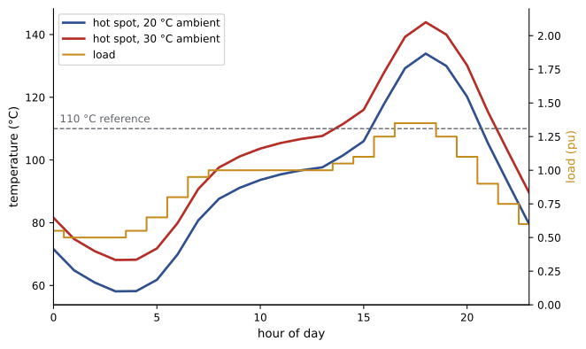
Because ageing is exponential in temperature, short excursions above 110 °C use up life quickly while cool periods use very little. On a 20 °C day the evening peak at 135% load consumes about 1.3 days of life per day; on a 30 °C day it consumes 3.3 days per day. Transferring 10% of load to another transformer brings ageing below normal. Utilities use such calculations to set seasonal ratings (higher in winter) and emergency ratings, and to schedule load transfers. Hot spots above about 140 °C also risk forming gas bubbles in the oil, which can cause dielectric failure, so loading guides cap peak hot-spot temperatures as well as total ageing.
Cooling classes
Cooling is described by four letters: the internal coolant (O for mineral oil, K for less-flammable liquids such as natural esters) and its circulation (N natural, F forced, D directed), then the external medium (A air, W water) and its circulation (N or F). An ONAN/ONAF/ONAF transformer might be rated 30/40/50 MVA: 30 MVA with natural oil and air flow, 40 MVA with the first stage of fans, 50 MVA with all fans running. Dry-type transformers, cooled by air with cast-resin or vacuum-impregnated windings, are used indoors where oil would be a fire hazard; they have insulation classes of 150 °C to 220 °C (Lesson 12).
Condition assessment and protection
Power transformers are monitored and tested throughout their lives to detect developing faults before they cause failure:
- Dissolved gas analysis (DGA) of oil samples is the most powerful single test. Overheating and electrical faults decompose oil and paper into characteristic gases: hydrogen from partial discharge, methane and ethylene from thermal faults in oil, acetylene from arcing, and carbon monoxide and dioxide from overheated paper. Ratio methods (Rogers, Duval triangle) interpret the pattern, and online DGA monitors give continuous readings on critical units.
- Oil quality tests measure moisture, dielectric breakdown voltage, acidity and interfacial tension; furan compounds in oil indicate paper degradation, estimating remaining insulation life.
- Electrical tests include winding resistance, turns ratio, insulation resistance and power factor (tan δ) of windings and bushings, and sweep frequency response analysis (SFRA), which detects winding movement after a through-fault or transport.
- Infrared thermography finds hot connections and blocked radiators.
Protection of large transformers uses differential relays, which compare currents entering and leaving the transformer (corrected for ratio and phase shift) and trip for internal faults, with second-harmonic restraint to ride through inrush (Lesson 3). Mechanical protections include the Buchholz relay, which detects gas accumulation and oil surges in conservator-type transformers, sudden pressure relays, pressure relief devices, and oil and winding temperature alarms and trips. Overcurrent relays or fuses provide backup protection, as set out in the electrical code rules described in Lesson 3.
Common mistakes
MistakeParalleling transformers with the same kVA but different vector groups.
InsteadPhase displacement must match exactly; Dyn1 cannot be paralleled with Dyn11.
MistakeAssuming paralleled units share load in proportion to rating.
InsteadLoad divides inversely with ohmic impedance; match per-unit impedance.
MistakeSizing a neutral for phase current on a harmonic-rich load.
InsteadTriplen harmonics add in the neutral; size it for the calculated neutral current.
MistakeRating a transformer only by its nameplate kVA.
InsteadUse loading guides; ambient and load cycle determine safe loading and ageing.
MistakeSkipping oil sampling on critical units.
InsteadTrend DGA and oil quality to detect faults early.
Summary and key terms
- Vector groups give connections and phase displacement; North American Δ-Y units have the LV side lagging 30°.
- Delta windings trap zero-sequence current; grounded wye secondaries need a delta to balance zero-sequence ampere-turns.
- Paralleled transformers need equal ratios, matching phase displacement and similar per-unit impedances.
- DETCs set long-term ratio; OLTCs regulate voltage under load and need maintenance.
- Harmonics increase winding losses (K-factor) and triplens add in the neutral.
- Insulation ageing doubles every 6 to 7 °C above a 110 °C hot spot; loading guides balance capacity and life.
- DGA, oil tests, electrical tests and differential and Buchholz protection guard against failure.
- Vector group
- Notation for winding connections and phase displacement.
- Zero-sequence current
- Equal, in-phase currents in all three phases.
- Grounding transformer
- A zigzag or wye-delta unit providing a neutral on an ungrounded system.
- Circulating current
- Current flowing between paralleled transformers, independent of load.
- On-load tap changer
- A device that changes taps while carrying load.
- K-factor
- A measure of harmonic heating effect on transformer windings.
- Hot-spot temperature
- The highest temperature in the winding insulation.
- Ageing acceleration factor
- The rate of insulation ageing relative to the reference temperature.
- Dissolved gas analysis
- Analysis of gases in oil to diagnose internal faults.
- Buchholz relay
- A relay detecting gas and oil surges in conservator transformers.
Practice problems
Work each problem on paper first, then reveal the answer to check.
What does Dyn11 mean?
Show answer
Delta HV, grounded wye LV, LV leading HV by 30°.
Can Dyn1 and Dyn11 be paralleled?
Show answer
No; they differ by 60°.
Two 1000 kVA units of 5% and 6% impedance share 2000 kVA. Approximate loading of each?
Show answer
1091 kVA and 909 kVA (inverse to impedance).
Size of one step on a ±10%, 32-step OLTC?
Show answer
0.625%.
K-factor of a current with fundamental 1.0 and 5th harmonic 0.4 pu?
Show answer
(1 + 0.16 × 25)/1.16 = 4.31.
Ageing acceleration factor at 117 °C?
Show answer
About 2.1.
Which gas indicates arcing in oil?
Show answer
Acetylene.
What does ONAF mean?
Show answer
Oil natural circulation, air forced (fans).
What does SFRA detect?
Show answer
Winding deformation or movement.
Why does a delta primary help with triplen harmonics?
Show answer
They circulate in the delta instead of flowing in the supply lines.
Lesson quiz · 5 questions
Score 60% or more to complete this lesson.
Create a free account to save your progress, take quizzes and earn a certificate.