
ELE-370 · Lesson 11 of 12 · 30 min
Permanent magnet, reluctance and small machines
The DC, induction and wound-field synchronous machines of the earlier lessons dominated electrical engineering for a century. Since the 1990s, cheap power electronics and strong rare-earth magnets have brought a new generation of machines into wide use: permanent magnet synchronous motors in electric vehicles, heat pumps and wind turbines; brushless DC motors in fans, drones and appliances; synchronous and switched reluctance motors that avoid magnets altogether; and stepper motors in printers and positioning systems. Single-phase induction and universal motors still run most household appliances. This lesson explains how these machines work, how they are controlled, and how to choose among them, building on the torque mechanisms of Lesson 2 and the dq control of Lesson 8.
Permanent magnet materials
A permanent magnet provides field flux without field current, eliminating field copper losses and the brushes or exciter needed to supply them. The key properties are the remanence \(B_r\), the flux density with no external field, and the coercivity \(H_c\), the reverse field that reduces flux to zero (Lesson 1 introduced the demagnetization curve).
| Material | Remanence \(B_r\) | Maximum operating temperature | Characteristics |
|---|---|---|---|
| Ferrite (ceramic) | 0.4 T | 250 °C | cheap, abundant, low energy; large magnets needed |
| Alnico | 1.2 T | 500 °C | low coercivity, easily demagnetized; instruments and sensors |
| Samarium cobalt | 1.0 to 1.1 T | 300 °C | excellent temperature stability; aerospace, high temperature |
| Neodymium iron boron (NdFeB) | 1.2 to 1.45 T | 80 to 220 °C depending on grade | strongest; coercivity falls with temperature; dysprosium added for high-temperature grades |
NdFeB magnets have made compact, efficient machines possible, but they lose coercivity as temperature rises, and a large reverse field from stator current, for example during a short circuit or aggressive field weakening on a hot day, can demagnetize them irreversibly. Their supply also depends heavily on rare-earth mining and processing concentrated in a few countries, which has driven interest in ferrite-assisted and magnet-free designs and in recycling.
Permanent magnet synchronous motors
A permanent magnet synchronous motor (PMSM) has a three-phase stator like an induction or synchronous machine (Lesson 6) and a rotor carrying magnets. Rotor construction falls into two families:
- Surface-mounted PM (SPM) rotors have magnets glued to the rotor surface, retained by a sleeve at high speed. Because magnet material has a permeability close to air, the effective air gap is large and nearly the same along both axes, so \(L_d \approx L_q\) and there is no reluctance torque. SPM motors are used in servo drives and direct-drive generators.
- Interior PM (IPM) rotors have magnets buried in slots in the rotor laminations. Iron paths between the magnets make the q-axis inductance larger than the d-axis inductance, so the rotor produces reluctance torque in addition to magnet torque. Magnets are mechanically protected and less exposed to demagnetizing fields. Most electric vehicle traction motors are IPM machines.
In the dq reference frame aligned with the magnet flux (Lesson 8), the torque is
The first term is magnet torque; the second, which is positive when \(i_d\) is negative and \(L_q > L_d\), is reluctance torque. For a given current magnitude, the controller chooses the current angle that gives the most torque, a strategy called maximum torque per ampere (MTPA).
import numpy as np

# Interior permanent magnet (IPM) motor for a vehicle: torque versus current angle, and maximum torque per ampere (MTPA)
p = 8                                   # poles
psi_m = 0.075                           # magnet flux linkage (Wb, peak per phase)
Ld, Lq = 0.20e-3, 0.55e-3               # d- and q-axis inductances (H); Lq > Ld for an IPM rotor
I = 300.0                               # current magnitude (A peak)

def torque(beta):                        # beta: current angle from the q axis toward negative d
    i_d, i_q = -I * np.sin(beta), I * np.cos(beta)
    T_mag = 1.5 * p / 2 * psi_m * i_q
    T_rel = 1.5 * p / 2 * (Ld - Lq) * i_d * i_q
    return T_mag, T_rel

for deg in (0, 15, 30, 45, 60):
    Tm, Tr = torque(np.radians(deg))
    print(f"current angle {deg:2d} deg: magnet torque {Tm:6.1f} N m + reluctance torque {Tr:6.1f} N m = {Tm + Tr:6.1f} N m")
betas = np.radians(np.linspace(0, 89, 891))
tot = [sum(torque(b)) for b in betas]
k = int(np.argmax(tot))
print(f"MTPA angle {np.degrees(betas[k]):.1f} deg gives {tot[k]:.1f} N m, {tot[k] / tot[0] - 1:.0%} more than with i_d = 0")
# Back EMF at top speed if the inverter stops switching: the magnets keep generating
for rpm in (4000, 12000, 16000):
    we = rpm * 2 * np.pi / 60 * p / 2
    E_line = np.sqrt(3) * we * psi_m / np.sqrt(2)
print(f"{rpm:5d} rpm: open-circuit back EMF {E_line:5.0f} V rms line-to-line (peak {E_line * np.sqrt(2):5.0f} V) against a 400 V battery")current angle 0 deg: magnet torque 135.0 N m + reluctance torque 0.0 N m = 135.0 N m current angle 15 deg: magnet torque 130.4 N m + reluctance torque 47.2 N m = 177.6 N m current angle 30 deg: magnet torque 116.9 N m + reluctance torque 81.8 N m = 198.8 N m current angle 45 deg: magnet torque 95.5 N m + reluctance torque 94.5 N m = 190.0 N m current angle 60 deg: magnet torque 67.5 N m + reluctance torque 81.8 N m = 149.3 N m MTPA angle 33.4 deg gives 199.6 N m, 48% more than with i_d = 0 4000 rpm: open-circuit back EMF 154 V rms line-to-line (peak 218 V) against a 400 V battery 12000 rpm: open-circuit back EMF 462 V rms line-to-line (peak 653 V) against a 400 V battery 16000 rpm: open-circuit back EMF 616 V rms line-to-line (peak 871 V) against a 400 V battery
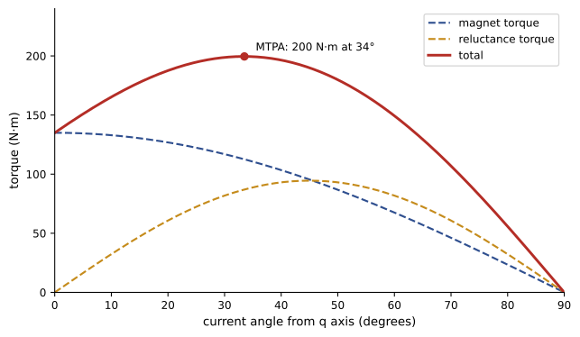
Advancing the current by about 33° raises torque by nearly half compared with putting all the current on the q axis, at no extra current, so the inverter and copper losses are the same. This is why IPM rotors dominate traction.
Field weakening and its hazards
The back EMF of a PMSM rises in proportion to speed, \(E = \omega_e \psi_m\). Above base speed, the inverter cannot supply enough voltage to drive current against it, so the controller injects negative d-axis current that opposes the magnet flux, reducing the effective flux and extending the speed range at roughly constant power. IPM motors are well suited to this because their larger q-axis inductance and saliency give a wide constant-power range. Field weakening has a hazard: if the inverter stops switching at high speed (a fault or an emergency shutdown), the magnets still generate the full back EMF. As the code shows, at 12,000 rpm this motor's back EMF peaks at about 650 V line-to-line, far above the 400 V battery, so current flows uncontrolled through the inverter's diodes into the battery, producing braking torque and possible overvoltage. Designers limit the magnet flux, specify inverter components for the back EMF at maximum speed, or use an active short-circuit strategy that shorts the three phases through the inverter switches.
Brushless DC motors
A brushless DC (BLDC) motor (introduced in Lesson 5) is a PM machine designed for trapezoidal back EMF and driven with six-step commutation: at any time two of the three phases conduct, and the inverter switches to the next pair every 60 electrical degrees, using three Hall sensors or back-EMF zero-crossing detection on the idle phase to know the rotor position. The control is simple and cheap, which suits fans, pumps, power tools, drones and computer cooling. Commutation produces torque ripple at six times the electrical frequency, which is acceptable for most of these uses; sinusoidal (FOC) drives of PMSMs give smoother torque for servo and traction applications. The motor's speed is set by the DC voltage applied, as in a DC machine: no-load speed is the supply voltage divided by the back-EMF constant \(k_e\), and torque is \(k_t I\), where in SI units \(k_t = k_e\).
Worked problem
BLDC motor constants
A 24 V BLDC fan motor has a back-EMF constant of 0.012 V/(rad/s) and winding resistance (line to line) of 0.4 Ω. Estimate the no-load speed, stall current and stall torque, and the speed at 0.05 N·m load.
Show solution
- No-load speed: \(24/0.012 = 2{,}000\) rad/s = 19,100 rpm.
- Stall current: \(24/0.4 = 60\) A; stall torque \(0.012 \times 60 = 0.72\) N·m.
- At 0.05 N·m: \(I = 0.05/0.012 = 4.17\) A; back EMF \(= 24 - 4.17 \times 0.4 = 22.3\) V; speed \(= 22.3/0.012 = 1{,}861\) rad/s = 17,800 rpm.
Answer: About 19,100 rpm at no load and 17,800 rpm at 0.05 N·m. The stall current of 60 A would destroy the motor quickly, so the controller limits current; this linear speed-torque behaviour is exactly that of a permanent magnet DC motor.
Synchronous reluctance and switched reluctance motors
Reluctance machines produce torque from rotor saliency alone (Lesson 2), with no magnets and no rotor windings, so their rotors are cheap, robust and tolerate high temperatures.
- Synchronous reluctance motors (SynRM) have a conventional distributed three-phase stator and a rotor of laminations with flux barriers that make \(L_d\) much larger than \(L_q\) (with axes defined along the high-permeance direction). Driven by a vector-controlled inverter, they run at synchronous speed with efficiencies at or above IE4, but with a lower power factor than induction motors, so the drive must supply more current. PM-assisted SynRMs add a small amount of ferrite in the barriers to improve power factor. Several manufacturers sell SynRM motor and drive packages for pumps and fans.
- Switched reluctance motors (SRM) have salient poles on both stator and rotor, for example 12 stator poles and 8 rotor poles, with concentrated coils on the stator poles. Each phase is energized in turn as rotor poles approach alignment, pulling the rotor round. The converter needs only unidirectional current. SRMs are extremely robust and fault tolerant and suit high temperatures and speeds, but produce significant torque ripple and acoustic noise because torque comes in pulses as each phase takes over. They are used in some appliances, mining equipment, and are studied for vehicles to avoid rare-earth magnets.
Stepper motors
Stepper motors move in precise angular increments in response to pulses, so they can position a load without a feedback sensor (open-loop). A hybrid stepper, the most common type, combines a permanent magnet with toothed rotor and stator cores; a typical motor has 200 steps per revolution (1.8° per step). Drivers energize the two phases in sequence: full steps, half steps, or microsteps, in which the phase currents follow sine and cosine values so that the rotor takes intermediate positions.
import numpy as np

# Stepper motor resolution and a capacitor-run single-phase motor
for steps in (200, 400):
    for micro in (1, 16):
        res = 360 / (steps * micro)
        print(f"{steps} full steps per rev, {micro:2d} microsteps: {res:.4f} deg per step; lead screw 5 mm per rev moves {5 / (steps * micro) * 1000:6.2f} um per step")

# Capacitor-run motor: choose C so that the auxiliary winding current leads the main winding current by 90 degrees at running
f, V = 60.0, 120.0
w = 2 * np.pi * f
Zm = 8.0 + 10.0j                         # main winding impedance at running speed (ohms)
Za = 30.0 + 12.0j                         # auxiliary winding impedance (ohms)
Im = V / Zm
phi_m = np.angle(Im)
# Want angle(Ia) = phi_m + 90 deg, with Ia = V / (Za - j Xc)
target = phi_m + np.pi / 2
Xc = Za.imag + Za.real * np.tan(target)  # angle(Za - j Xc) = -target
C = 1 / (w * Xc)
Ia = V / (Za - 1j * Xc)
print(f"main winding current {abs(Im):.1f} A at {np.degrees(phi_m):.1f} deg")
print(f"capacitor {C * 1e6:.0f} uF (Xc = {Xc:.1f} ohm) gives auxiliary current {abs(Ia):.1f} A at {np.degrees(np.angle(Ia)):.1f} deg: {np.degrees(np.angle(Ia) - phi_m):.0f} deg apart")200 full steps per rev, 1 microsteps: 1.8000 deg per step; lead screw 5 mm per rev moves 25.00 um per step 200 full steps per rev, 16 microsteps: 0.1125 deg per step; lead screw 5 mm per rev moves 1.56 um per step 400 full steps per rev, 1 microsteps: 0.9000 deg per step; lead screw 5 mm per rev moves 12.50 um per step 400 full steps per rev, 16 microsteps: 0.0563 deg per step; lead screw 5 mm per rev moves 0.78 um per step main winding current 9.4 A at -51.3 deg capacitor 74 uF (Xc = 36.0 ohm) gives auxiliary current 3.1 A at 38.7 deg: 90 deg apart
Microstepping gives fine resolution and smoother motion, though the actual positional accuracy is limited by the motor's detent torque and load; typical accuracy is about ±5% of a full step. A stepper's torque falls with speed because winding inductance limits how fast current can rise, so drivers use higher supply voltages with current chopping. If the load torque exceeds the motor's torque, the motor loses steps, and an open-loop controller does not know the position has been lost, a common failure in 3D printers and machine tools. Closed-loop steppers add an encoder to detect and correct lost steps.
Single-phase induction motors
A single-phase winding produces a pulsating field, which is the sum of equal forward and backward rotating fields (Lesson 6). A stationary rotor therefore receives equal and opposite torques and does not start; once spinning, it keeps running in either direction because the forward field dominates. To start, single-phase motors add an auxiliary winding displaced 90° in space, carrying current shifted in time, which together with the main winding produces an approximately rotating field:
- Split-phase motors use an auxiliary winding with high resistance and low reactance, giving a phase shift of about 30°; a centrifugal switch disconnects it at about 75% speed. They are cheap with moderate starting torque, used in fans and small pumps.
- Capacitor-start motors add a capacitor in series with the auxiliary winding for a phase shift near 90° and high starting torque, used in compressors and well pumps.
- Permanent split capacitor (PSC) motors keep a smaller run capacitor in circuit, giving quieter, more efficient running but low starting torque; common in HVAC blowers and fans.
- Capacitor-start capacitor-run motors combine both for high starting torque and good running efficiency.
- Shaded-pole motors use a copper ring around part of each pole to delay flux there; very cheap and inefficient (20 to 30%), used in small fans.
The capacitor is chosen to set the phase shift. In the calculation with the stepper example above, a capacitor of about 74 µF puts the auxiliary current 90° ahead of the main winding current at running speed. At standstill the winding impedances are different, so one capacitor cannot give the ideal shift both when starting and when running, which is why the best-performing motors use separate start and run capacitors.
Single-phase motors are less efficient and noisier than three-phase motors, and in HVAC and appliances they are being replaced by electronically commutated motors (ECM), which are BLDC motors with integrated drives running from single-phase supplies, offering variable speed and efficiencies of 70 to 80% in small sizes compared with 40 to 60% for PSC motors.
Universal motors and linear motors
A universal motor is a series-wound DC motor (Lesson 5) with laminated field and armature cores so that it runs on AC as well: reversing the current reverses both field and armature, so torque keeps its direction. It is light, cheap, gives very high speeds (20,000 to 35,000 rpm) and high starting torque, which suits vacuum cleaners, power tools and kitchen appliances, but its brushes wear and it is noisy. Linear motors unroll a rotary machine into a flat form, producing thrust directly, with no gears or screws; linear PM motors drive precision stages and machine tools, and linear induction motors propel some transit systems, including Vancouver's SkyTrain Expo and Millennium lines.
Choosing a motor
| Type | Efficiency | Cost | Control needed | Typical applications |
|---|---|---|---|---|
| Three-phase induction (IE3) | high | low | none (line start) or VFD | pumps, fans, conveyors, compressors |
| PMSM (IPM or SPM) | very high (IE4, IE5) | high (magnets) | inverter with position sensing | EV traction, heat pumps, servo, wind |
| BLDC or ECM | high in small sizes | moderate | simple six-step inverter | fans, appliances, drones, HVAC blowers |
| Synchronous reluctance | very high (IE4) | moderate | vector inverter | pumps and fans, magnet-free |
| Switched reluctance | high | low motor, special converter | dedicated converter | rugged, high-temperature or high-speed duty |
| Stepper | low | low | step driver | open-loop positioning, printers |
| Single-phase induction | low to moderate | very low | none | small appliances, legacy HVAC |
| Universal | moderate | very low | none or phase control | vacuums, power tools, mixers |
Common mistakes
MistakeIgnoring magnet temperature in a PM motor design.
InsteadCheck demagnetization at the highest temperature and largest reverse current.
MistakeAssuming a PM motor is safe when the inverter is off at high speed.
InsteadBack EMF can exceed the DC bus; design for uncontrolled generation.
MistakeRunning an IPM motor with i_d = 0.
InsteadUse MTPA control to exploit reluctance torque.
MistakeAssuming an open-loop stepper always knows its position.
InsteadExcess load causes lost steps; size torque with margin or use closed loop.
MistakeReplacing a failed run capacitor with any value.
InsteadUse the specified capacitance and voltage rating.
Summary and key terms
- NdFeB magnets give strong fields but lose coercivity with temperature; ferrite and magnet-free designs reduce rare-earth dependence.
- SPM rotors have no saliency; IPM rotors add reluctance torque, exploited by MTPA control.
- Field weakening extends PMSM speed range, but back EMF at high speed is a hazard if the inverter stops.
- BLDC motors use six-step commutation and behave like PM DC motors.
- SynRM and SRM produce torque from saliency alone, without magnets.
- Steppers position in open loop; microstepping improves smoothness; excess load loses steps.
- Single-phase motors need an auxiliary winding and often a capacitor to start; ECMs are replacing them.
- Remanence
- The flux density of a magnet with no external field.
- Coercivity
- The reverse field that reduces a magnet's flux to zero.
- Interior PM rotor
- A rotor with magnets buried in the laminations, giving saliency.
- MTPA
- Maximum torque per ampere control of the current angle.
- Six-step commutation
- Switching two of three phases in turn every 60 electrical degrees.
- Synchronous reluctance motor
- A motor with a flux-barrier rotor producing reluctance torque at synchronous speed.
- Switched reluctance motor
- A doubly salient motor energized phase by phase.
- Microstepping
- Driving a stepper with sinusoidal phase currents for intermediate positions.
- Capacitor-start motor
- A single-phase motor with a capacitor in the auxiliary winding for starting.
- Electronically commutated motor
- A BLDC motor with an integrated drive, used in HVAC.
Practice problems
Work each problem on paper first, then reveal the answer to check.
Why does an SPM motor have no reluctance torque?
Show answer
Magnets have near-air permeability, so \(L_d \approx L_q\).
Sign of i_d for reluctance torque in an IPM with L_q > L_d?
Show answer
Negative.
Torque of an SPM motor with p = 6, ψ_m = 0.1 Wb, i_q = 50 A?
Show answer
\(1.5 \times 3 \times 0.1 \times 50 = 22.5\) N·m.
Electrical frequency of an 8-pole PMSM at 6,000 rpm?
Show answer
400 Hz.
No-load speed of a 48 V BLDC with k_e = 0.05 V/(rad/s)?
Show answer
960 rad/s ≈ 9,170 rpm.
Step angle of a 200-step motor with 8 microsteps?
Show answer
0.225°.
Why does a single-phase motor need an auxiliary winding?
Show answer
A single winding gives a pulsating field with no starting torque.
What does a centrifugal switch do?
Show answer
Disconnects the starting winding at about 75% speed.
Why does a universal motor run on AC?
Show answer
Field and armature currents reverse together, so torque direction is unchanged.
Name one advantage of SRMs.
Show answer
No magnets, robust rotor, high temperature and speed capability.
Lesson quiz · 5 questions
Score 60% or more to complete this lesson.
Create a free account to save your progress, take quizzes and earn a certificate.