
DCT-220 · Lesson 4 of 12 · 19 min
UPS topologies: double conversion, line-interactive and eco mode
The uninterruptible power supply is the heart of a data centre's power plant. It is the reason a utility failure does not reach the servers, and it is the source of more alarms on a typical shift than any other piece of electrical equipment. This lesson explains how the main UPS designs work, what the operating modes mean, how UPS systems are built from modules, and how to read the front panel and the monitoring screens. Batteries are the subject of lesson 5 and bypass paths of lesson 6; here the focus is on the power electronics and the modes they operate in.
What a UPS has to do
A data centre UPS has three jobs. First, it must keep supplying the load without interruption when its input fails, drawing energy from its batteries until the generators take over or the batteries run down. Second, it must condition the power the rest of the time, protecting the load from the sags, swells, transients and harmonics described in lesson 2. Third, it must do both reliably for years while losing as little energy as possible. Different UPS designs balance these jobs differently.
Double conversion
Almost every large data centre UPS is a double-conversion design, also called online. Incoming AC power goes first through a rectifier, which converts it to DC. The DC feeds a DC bus, to which the battery is connected, and then an inverter, which converts the DC back to clean, regulated AC for the load. Because the load is always fed by the inverter, a failure of the input changes nothing at the output: the rectifier simply stops supplying the DC bus and the battery takes over, with no transfer and no gap. The output is also isolated from the input's disturbances, because the inverter makes a fresh waveform.
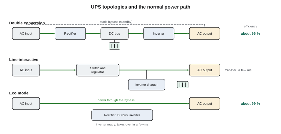
The cost of double conversion is efficiency. Converting all the power twice loses energy in each stage. Modern large UPS modules reach about 95 to 97 % efficiency in double conversion at typical loads, lower at light loads. Every percentage point of loss is heat in the UPS room that must be cooled, and electricity paid for.
Line-interactive and standby designs
Smaller UPS systems, such as the units in network closets or inside some customer racks, are often line-interactive. In normal operation, the load is fed from the utility through a transformer or regulator that corrects small voltage changes. An inverter-charger keeps the battery charged. When the input fails or goes outside its limits, a switch disconnects the input and the inverter takes over, with a transfer time of a few milliseconds. Standby or offline designs are similar but with less regulation. These designs are efficient and inexpensive, but the transfer gap and the lack of full conditioning make them unsuitable as the main UPS for a data hall.
Eco mode and other high-efficiency modes
Many double-conversion UPS systems offer a high-efficiency mode, often called eco mode. In eco mode, the load is fed through the static bypass path straight from the input, with the inverter running in standby, ready to take over. Efficiency rises to about 99 %, because power is not being converted. When the input goes outside its limits, the UPS switches the load to the inverter in a few milliseconds. Some newer designs add an intermediate mode in which the inverter runs in parallel to correct harmonics and power factor while most power passes through the bypass.
Eco mode saves a great deal of energy, but it exposes the load to more of the input's disturbances and adds a transfer. Operators decide carefully when to use it. At Stonebridge, Halls B and C run their UPS systems in an advanced eco mode by agreement with the cloud tenant, because its servers tolerate the brief transfers. Hall A and Hall D run in double conversion: Hall A because many enterprise customers' contracts specify it, and Hall D because the AI racks' load changes so quickly that Corvid AI asked for full conditioning.
# UPS losses and cooling cost: double conversion vs eco mode (illustrative)
load_kw = 1600
hours = 8760
price = 0.075            # CAD per kWh, illustrative
modes = {"double conversion": 0.965, "eco mode": 0.990}
for mode, eff in modes.items():
    loss_kw = load_kw / eff - load_kw
    loss_kwh = loss_kw * hours
    cooling_kwh = loss_kwh * 0.25    # extra energy to remove the heat, illustrative
    cost = (loss_kwh + cooling_kwh) * price
print(f"{mode:18s}: losses {loss_kw:6.1f} kW, {loss_kwh / 1000:7.0f} MWh/yr, cost {cost:,.0f} CAD/yr")double conversion : losses 58.0 kW, 508 MWh/yr, cost 47,658 CAD/yr eco mode : losses 16.2 kW, 142 MWh/yr, cost 13,273 CAD/yr
For one 1.6 MW UPS system, the difference is several hundred megawatt-hours a year. Across a campus, that is why the choice of mode is a business decision as well as a technical one.
Modules, frames and systems
Large UPS systems are built from modules. Each module is a complete rectifier, inverter and control unit rated for a few hundred kilowatts. Several modules are installed in a frame or as separate cabinets and run in parallel, sharing the load. Stonebridge's UPS-A2, serving the A side of Hall A, has four 500 kW modules for a 2,000 kW system; UPS-B2 is identical on the B side. The modules share the load equally: at today's 600 kW per side, each carries 150 kW, or 30 % of its rating. If the B side failed, UPS-A2 would carry the whole hall, 1,200 kW, at 60 % per module.
Modular systems have two advantages. They can be expanded by adding modules as load grows, and they can be redundant within themselves: a system needing three modules for its load can have four, so one can fail or be serviced while the others carry the load. A module can usually be isolated and removed while the system stays online, a job done by the UPS vendor's field engineer with Stonebridge's electrical team, as in the UPS-B2 module swap in DCT-120.
# Load per module, and what happens if one module goes offline (illustrative)
modules = 4
module_kw = 500
load_kw = 1200          # the whole Hall A load, as if the B side had failed
for online in (modules, modules - 1):
    per = load_kw / online
    pct = per / module_kw * 100
    state = "OK" if pct <= 90 else "OVERLOAD RISK"
    print(f"{online} modules online: {per:.0f} kW each ({pct:.0f} %) -> {state}")
capacity_lost_one = (modules - 1) * module_kw
print(f"Highest load that survives one module offline: {capacity_lost_one * 0.9:.0f} kW at 90 % per module")4 modules online: 300 kW each (60 %) -> OK 3 modules online: 400 kW each (80 %) -> OK Highest load that survives one module offline: 1350 kW at 90 % per module
Operating modes on the front panel
A UPS front panel or screen shows a mimic diagram of the power path, with the active path highlighted, and a status message. A technician should be able to recognize these states at a glance:
| Mode | What it means | Technician's response |
|---|---|---|
| Normal / online (double conversion) | Load fed through rectifier and inverter; battery charging or floating | None; record load and battery status on the round |
| Eco / high-efficiency | Load fed through bypass; inverter ready | None, where this is the hall's normal mode |
| On battery | Input lost or out of limits; load fed from battery through inverter | Urgent: check the input and the generators; inform the shift lead |
| On static bypass | Inverter off; load fed straight from input through static switch | Urgent: the load has no UPS protection; call critical facilities |
| On maintenance bypass | UPS isolated for work; load fed through external bypass | Expected only during planned work with a permit |
| Alarm / fault | A module, fan, battery or sensor has a problem | Read the message, record it, call critical facilities |
The two states that call for the fastest response are on battery, because the clock is running on the battery reserve, and on static bypass, because the load is now exposed to the input with no stored energy behind it. A UPS can go to static bypass by itself if it has an internal fault or an overload it cannot carry on its inverter, which is one reason the per-module load matters.
Overloads and load steps
A UPS inverter can carry a short overload, typically around 110 to 125 % for minutes and 150 % for a minute or less, depending on the design. Beyond that, the UPS transfers the load to static bypass so that the input can supply the extra current, for example to clear a downstream fault. Large sudden load steps are also demanding. AI training loads can swing by a large fraction of their power in fractions of a second as thousands of processors start and stop computing together. Hall D's UPS systems were chosen and set up with the vendor to handle those swings, and the batteries and inverters are sized with margin for them. When Corvid AI plans a large new training run, Carmen Ortiz notifies the operations team in advance.
Reading the UPS screens on the round
On the daily round, technicians record for each UPS system: the mode, the input voltage and current, the output voltage, current and kilowatts, the load as a percentage of capacity, the number of modules online, the battery status and estimated runtime, the room temperature and any active alarms. The monitoring system records the same values continuously, but the walk-round catches what sensors miss: a noisy fan, a strong smell of hot electronics, a filter clogged with dust, a door left open, or water on the floor.
# Daily UPS round: compare readings with limits (illustrative)
readings = {  # system: (mode, load %, modules online, runtime min, room temp)
    "UPS-A2": ("double conversion", 30, 4, 23.1, 24.0),
    "UPS-B2": ("double conversion", 30, 4, 22.9, 24.5),
    "UPS-C1": ("eco mode", 54, 6, 7.2, 23.5),
    "UPS-C2": ("static bypass", 55, 6, 7.0, 23.8),
}
normal = {"UPS-A2": "double conversion", "UPS-B2": "double conversion", "UPS-C1": "eco mode", "UPS-C2": "eco mode"}
for ups, (mode, load, mods, runtime, temp) in readings.items():
    issues = []
    if mode != normal[ups]: issues.append(f"mode is {mode}")
    if load > 80: issues.append("load high")
    if runtime < 5: issues.append("runtime low")
    if temp > 27: issues.append("room hot")
print(f"{ups}: " + ("; ".join(issues) + " -> call critical facilities" if issues else "normal"))UPS-A2: normal UPS-B2: normal UPS-C1: normal UPS-C2: mode is static bypass -> call critical facilities
Worked problem
Static bypass on UPS-C2
On his evening round, Jamal finds UPS-C2, serving the B side of Hall C, showing on static bypass with an inverter fault message. Its partner UPS-C1 is normal. The monitoring system raised the alarm two minutes earlier.
Show solution
- Jamal reads the screen without touching it: mode static bypass, alarm inverter fault module 3, load 55 %.
- He calls Roz and the shift lead, Dmitri, and reports exactly what the screen says.
- Dmitri marks the redundancy whiteboard: the B side of Hall C has no UPS protection; the A side is normal.
- Roz arrives, confirms the alarm and calls the UPS vendor's support line. The vendor asks her to leave the system on bypass until their engineer arrives, rather than trying to restart the inverters.
- The cloud tenant's operations team is informed through the agreed channel. All planned work in the Hall C electrical rooms is postponed.
- The vendor's engineer arrives two hours later, finds a failed gate driver board in module 3, isolates the module, and returns the system to normal operation on its remaining five modules.
Answer: The load never lost power: the static bypass carried it from the input, and the A side stayed fully protected. For two hours, though, a utility interruption would have dropped the B side of Hall C to the protection of the A side alone. Recognizing the mode instantly and reporting it accurately let the team limit that exposure.
Common mistakes
MistakeThinking eco mode means the UPS is off.
InsteadIn eco mode the inverter is ready and takes over within milliseconds.
MistakeTreating static bypass as normal because the load is up.
InsteadThe load has no UPS protection on that side; call critical facilities.
MistakeRestarting a UPS inverter after a fault.
InsteadRestarting is for the vendor or the critical facilities team, following the procedure.
MistakeAssuming four modules means four times the redundancy.
InsteadCheck the load: redundancy exists only if the remaining modules can carry it.
MistakeIgnoring a UPS room temperature rise.
InsteadHeat shortens battery and component life; report it.
Summary and key terms
- Double-conversion UPS systems feed the load through a rectifier and inverter at all times, so a lost input causes no transfer.
- Line-interactive and standby designs transfer to the inverter when the input fails and suit small loads.
- Eco mode feeds the load through the bypass for higher efficiency, with the inverter ready to take over.
- Large UPS systems are built from parallel modules that share the load and can provide internal redundancy.
- On battery and on static bypass are the two modes that call for the fastest response.
- Technicians read and record UPS modes, loads, runtime and alarms, and report anything abnormal.
- Double conversion
- A UPS design in which all power passes through a rectifier and an inverter.
- Rectifier
- A converter that changes AC to DC.
- Inverter
- A converter that changes DC to AC.
- Eco mode
- A high-efficiency UPS mode in which the load is fed through the bypass with the inverter on standby.
- Static bypass
- An electronic switch that connects the UPS input directly to its output.
- UPS module
- A self-contained rectifier, inverter and control unit that runs in parallel with others.
Practice problems
Work each problem on paper first, then reveal the answer to check.
Why is there no transfer when the input fails on a double-conversion UPS?
Show answer
The inverter always feeds the load; the battery simply replaces the rectifier as the DC source.
A 4-module system of 500 kW modules carries 1,500 kW. Is it redundant?
Show answer
No: three modules would each carry 500 kW, 100 %, with no margin.
Why might an operator choose double conversion over eco mode?
Show answer
Full conditioning and no transfer for sensitive loads or contracts that require it.
Which two UPS modes call for the fastest response?
Show answer
On battery and on static bypass.
Lesson quiz · 5 questions
Score 60% or more to complete this lesson.
Create a free account to save your progress, take quizzes and earn a certificate.