
DCT-220 · Lesson 1 of 12 · 20 min
The power chain from utility to rack
Every server in a data hall depends on a chain of equipment that starts many kilometres away at a power station and ends at a socket strip at the back of a rack. A data centre technician does not design that chain or work inside its energized parts, but they work beside it every day. They read its meters, answer its alarms, escort the electricians and vendors who maintain it, and are often the first person to notice that something along it has changed. This course follows the chain link by link: the utility service, the switchgear and transformers, the uninterruptible power supply (UPS) and its batteries, the bypass paths, the generators and transfer switches, the panels and busways in the hall, the rack power distribution units (PDUs), and finally the redundancy that ties it all together.
This first lesson draws the whole chain once, so that each later lesson has a place to fit. It also sets out the technician's role clearly. Since DCT-120, Jamal Pierce has been allowed to work alone on the data hall floor at Stonebridge Data's YUL-2 campus in Beauharnois. His mentor Roz Kerr now wants him to understand the electrical plant well enough to read the redundancy whiteboard without asking, to explain an alarm to a customer, and to know which questions to ask before anyone opens a panel.
The links in the chain
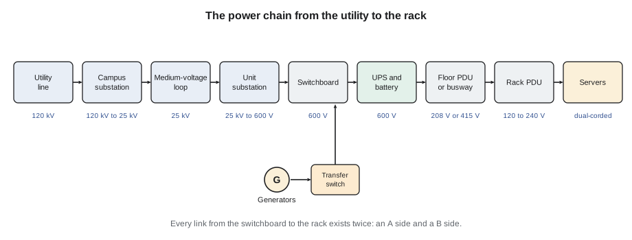
Electricity reaches the campus from the utility at high voltage, because high voltage carries large amounts of power over long distances with small losses. At YUL-2, Hydro-Québec supplies the campus at 120 kV. The campus substation steps this down to medium voltage, 25 kV, which is distributed around the campus in underground cables to unit substations beside each building. There, transformers step the voltage down again to the low voltage used inside the building, 600 V three-phase.
From the low-voltage switchboards, power goes to the UPS systems. A UPS keeps the load running from its batteries for the seconds or minutes between a utility failure and the generators taking over, and it cleans up the power the rest of the time. The UPS output feeds distribution boards and then floor-mounted PDUs or busways in the data hall. In Hall A, floor PDUs contain transformers that step 600 V down to 208Y/120 V for the older equipment. In Halls B, C and D, overhead busways carry 415Y/240 V straight to tap-off boxes above the racks. Finally, rack PDUs, the socket strips mounted vertically in each cabinet, distribute power to the individual servers and switches.
Two paths to every rack
Stonebridge's halls are built so that every rack is fed by two independent power paths, called the A side and the B side. Each side has its own UPS system, its own distribution boards, its own PDUs or busways and its own rack PDU. Most IT equipment has two power supplies, one plugged into each side, and either supply can carry the whole load of the device. If anything fails on one side, from a UPS module to a single rack PDU, the equipment keeps running on the other. This arrangement is called 2N distribution: two complete systems, each able to carry the whole load. Lesson 11 looks at redundancy in detail; for now, the point is that every link drawn above exists twice in the data hall, once for A and once for B.
Further upstream, the paths share some equipment. Both UPS systems are fed from the same campus substation and the same generator plant, although the switchboards and generator connections are arranged so that a single fault does not take out both. The generators are installed as N+1: enough generators to carry the load plus one spare. The utility itself is the one link Stonebridge cannot duplicate fully, which is why the generators and UPS batteries exist.
Why the chain has so many links
A technician new to data centres sometimes asks why power is not simply brought to the rack at one voltage. Each link has a job. Transmission and medium voltage keep the current small, so that cables can be thinner and losses lower. The low-voltage switchboard divides the power among many loads and protects each with a breaker. The UPS isolates the IT load from the utility's sags, spikes and interruptions. The PDU or busway brings power close to the racks in manageable branches. The rack PDU gives each device its own outlet and lets the customer measure and sometimes switch each one.
Each link also has a cost. Every transformer, rectifier and inverter wastes a little energy as heat, which the cooling system must then remove. A modern double-conversion UPS might be 96 to 97 % efficient at a good load, and a transformer 98 to 99 %. These losses are small one by one but add up across a chain, and they are part of why a data centre's power usage effectiveness (PUE) is above 1.0. The code below follows one kilowatt of IT load back up the chain to show how much power the utility has to deliver for it before cooling is even counted.
# How much utility power does 1,000 kW of IT load need? (electrical losses only, illustrative)
it_load_kw = 1000.0
stages = [  # (stage, efficiency at this load)
    ("rack PDUs and cords", 0.995),
    ("floor PDU transformer, 600 V to 208 V", 0.975),
    ("UPS (double conversion)", 0.965),
    ("switchboard and cables", 0.995),
    ("unit substation transformer", 0.985),
]
p = it_load_kw
print(f"{'stage':32s}{'input kW':>10s}{'loss kW':>9s}")
for name, eff in stages:
    p_in = p / eff
    print(f"{name:32s}{p_in:10.1f}{p_in - p:9.1f}")
    p = p_in
print(f"Utility power for the IT load: {p:.1f} kW")
print(f"Electrical losses: {p - it_load_kw:.1f} kW ({(p - it_load_kw) / it_load_kw * 100:.1f} % of the IT load)")stage input kW loss kW rack PDUs and cords 1005.0 5.0 floor PDU transformer, 600 V to 208 V 1030.8 25.8 UPS (double conversion) 1068.2 37.4 switchboard and cables 1073.5 5.4 unit substation transformer 1089.9 16.3 Utility power for the IT load: 1089.9 kW Electrical losses: 89.9 kW (9.0 % of the IT load)
About seven or eight per cent of the IT load is lost as heat in the electrical chain itself. That heat appears in the electrical rooms, UPS rooms and halls, and every kilowatt of it has to be cooled. This is one reason newer halls use 415 V busways with no floor PDU transformer: removing a link removes its losses.
Three-phase power in one paragraph
Almost all the power in a data centre is three-phase alternating current. Three conductors carry currents that rise and fall a third of a cycle apart, so the total power flows smoothly instead of pulsing. A three-phase supply is described by its line-to-line voltage, measured between any two phase conductors, and its line-to-neutral voltage, measured between one phase and the neutral. The two differ by a factor of the square root of three, about 1.732: 208 V line to line is 120 V line to neutral, and 415 V is 240 V. The 600 V building supply has a line-to-neutral voltage of 347 V, used for lighting. The power carried by a balanced three-phase circuit is found from the formula below.
Here P is the real power in watts, V is the line-to-line voltage, I is the current in each phase conductor and PF is the power factor, the fraction of the apparent power that does useful work. Modern server power supplies have power factors close to 0.95 to 0.99. Technicians use this formula constantly to turn a current reading on a meter into kilowatts, or to check whether a feed can carry a planned load.
import math
# Current drawn by a 400 kW load at each voltage in the chain (balanced three-phase, PF 0.95)
load_kw = 400.0
pf = 0.95
for label, v_ll in [("medium voltage", 25000), ("building low voltage", 600), ("busway", 415), ("floor PDU output", 208)]:
    i = load_kw * 1000 / (math.sqrt(3) * v_ll * pf)
print(f"{label:24s}{v_ll:>8,.0f} V{i:>10,.0f} A per phase")medium voltage 25,000 V 10 A per phase building low voltage 600 V 405 A per phase busway 415 V 586 A per phase floor PDU output 208 V 1,169 A per phase
The same 400 kW that needs only about 10 amperes at medium voltage needs over a thousand amperes at 208 V. That is why the low-voltage parts of the chain are short and heavy, and why a modest change in rack load can matter to a branch circuit even when it is invisible upstream.
Where the technician fits
In Quebec and Virginia alike, work on electrical equipment is done by licensed electricians and qualified electrical workers. A data centre technician is treated as an unqualified person for electrical work, as DCT-120 explained. That still leaves a great deal of the electrical plant in the technician's daily work:
- Reading meters and screens: UPS front panels, switchboard power meters, PDU and busway displays, and the monitoring system, without opening any cover.
- Walking the plant: daily rounds of the electrical rooms, UPS rooms, battery room and generator yard, looking and listening for anything abnormal and recording readings.
- Answering alarms: going to the equipment, confirming what the alarm shows, and calling the critical facilities team or the shift lead.
- Rack-level work: plugging and unplugging equipment into rack PDUs, checking A and B cords, reading per-outlet current and resetting rack PDU breakers where the site procedure allows.
- Escorting and permits: escorting electricians and vendors, checking that their permits and lockouts match the job, and keeping the area clear.
- Communication: telling customers what is happening in plain words, and recording events accurately in tickets.
What a technician does not do is open switchgear, operate breakers on distribution equipment, work inside UPS cabinets or on battery terminals, or operate transfer switches or bypass breakers, except where a site procedure specifically trains and authorizes them for a defined step under supervision. At Stonebridge, the critical facilities technicians like Roz hold the electrical operating authority; Jamal assists and observes.
The single-line diagram
The map of the power chain is the single-line diagram. It draws each three-phase circuit as one line, with symbols for breakers, transformers, UPS modules, generators and transfer switches, and labels showing names, ratings and voltages. Every piece of equipment in the plant carries a name that matches the diagram, such as SWBD-A2 for a switchboard or PDU-A2-05 for a floor PDU. When an alarm says that PDU-A2-05 has a high load, the technician can find it on the diagram, see which UPS feeds it, and see which racks it serves.
Stonebridge keeps the single-line diagrams on the wall of each electrical room and in the monitoring system. Roz asks Jamal to trace one rack, A-31-03, from the rack PDUs back to the utility on both the A and B sides, writing down every piece of equipment on the way. It takes him forty minutes the first time. By the end of this course he should be able to do it in five.
| Name pattern | Equipment | Example |
|---|---|---|
| SUB-x | Campus substation | SUB-1 |
| USS-xx | Unit substation (medium- to low-voltage transformer) | USS-A2 |
| SWBD-xx | Low-voltage switchboard | SWBD-A2, SWBD-B2 |
| GEN-xx | Generator | GEN-A1, GEN-A2, GEN-A3 |
| ATS-xx | Automatic transfer switch | ATS-A2 |
| UPS-xx | UPS system (several modules) | UPS-A2, UPS-B2 |
| PDU-xx-nn | Floor power distribution unit | PDU-A2-05 |
| BW-xx-nn | Overhead busway run | BW-D1-04 |
| RPP-xx-nn | Remote power panel | RPP-A2-03 |
Worked problem
Turning a meter reading into kilowatts
During his round, Jamal reads the output meter of floor PDU PDU-A2-05: 208 V line to line, 412 A, 409 A and 418 A on the three phases, power factor 0.97. Its nameplate rating is 300 kVA. Roz asks him how much load it carries and how close it is to its rating.
Show solution
- Average the three phase currents: (412 + 409 + 418) / 3 = 413 A.
- Apparent power S = 1.732 × 208 V × 413 A = 148,800 VA, about 149 kVA.
- Real power P = 149 kVA × 0.97 = 144 kW.
- Loading = 149 kVA / 300 kVA = 50 %.
Answer: The PDU carries about 144 kW, half its rating. Because it is one half of a 2N pair, it must be able to carry its partner's load too if PDU-B2-05 fails, so Stonebridge plans each PDU of a pair to stay below about 40 % of its rating in normal operation. At 50 %, this PDU is above the planning limit and Jamal reports it to Dmitri.
Common mistakes
MistakeThinking a UPS alarm only affects one rack.
InsteadTrace the equipment on the single-line diagram; one UPS may feed hundreds of racks.
MistakeReading 208 V and 120 V as two different supplies.
InsteadThey are line-to-line and line-to-neutral voltages of the same three-phase supply.
MistakeTreating the A and B sides as interchangeable spare capacity.
InsteadEach side must be able to carry the whole load if the other fails, so each is loaded to less than half.
MistakeOpening a panel to read a value that is not on the display.
InsteadTechnicians read only external meters and screens; anything else is for qualified electrical workers.
MistakeForgetting that every link wastes energy.
InsteadLosses become heat in electrical rooms and halls that must be cooled.
Summary and key terms
- Power reaches the rack through the utility, substation, medium-voltage distribution, unit substation, switchboard, UPS, PDU or busway, and rack PDU.
- Voltage steps down at each transformer: high voltage for distance, low voltage for use.
- Every rack has A and B power paths; each must be able to carry the whole load.
- Three-phase power is P = 1.732 × V × I × PF; technicians use it to turn meter readings into kilowatts.
- Each link in the chain loses some energy as heat, adding to the cooling load and the PUE.
- Technicians read, walk, report and escort; qualified electrical workers operate and open the equipment.
- Single-line diagram
- A drawing of the electrical system that shows each three-phase circuit as one line, with its equipment and ratings.
- UPS
- Uninterruptible power supply: equipment that keeps the load running from stored energy when the input fails.
- PDU
- Power distribution unit: a floor-standing unit that distributes power to a row of racks, or a strip of outlets in a rack.
- 2N distribution
- Two complete power paths to each rack, each able to carry the whole load.
- Line-to-line voltage
- The voltage measured between two phase conductors of a three-phase supply.
- Power factor
- The ratio of real power to apparent power in an AC circuit.
Practice problems
Work each problem on paper first, then reveal the answer to check.
What is the line-to-neutral voltage of a 415 V three-phase supply?
Show answer
About 240 V (415 divided by 1.732).
Why is power distributed at medium voltage around the campus?
Show answer
Higher voltage means lower current for the same power, so smaller cables and lower losses.
A floor PDU of a 2N pair reads 45 % load. Why is that a concern?
Show answer
If its partner fails it must carry both loads, about 90 %, leaving little margin; the planning limit is about 40 %.
Name three things a technician may do with the electrical plant and one they may not.
Show answer
May read meters, walk rounds, answer alarms, escort, work at rack PDUs; may not open switchgear or operate distribution breakers.
Lesson quiz · 5 questions
Score 60% or more to complete this lesson.
Create a free account to save your progress, take quizzes and earn a certificate.