
DCT-220 · Lesson 2 of 12 · 20 min
Utility service, medium voltage and substations
The utility is the first link in the power chain and the only one a data centre does not own. Its reliability, its voltage quality and the size of connection it can offer shape everything downstream: how big the UPS batteries are, how many generators there are and how often they run. A technician never operates utility equipment or the medium-voltage switchgear, but they see the effects of the utility every day in the power quality readings, and they are often the first to notice when a feed is lost. This lesson covers how the campus is supplied, what happens inside the substation and medium-voltage system, and how to read the power quality events the utility produces.
How the campus is supplied
Large data centres connect to the utility's transmission or sub-transmission network, because their loads are far bigger than a distribution feeder can carry. A campus like YUL-2 takes power from Hydro-Québec at 120 kV on two separate lines that arrive from different directions. Each line ends at a high-voltage breaker in the campus substation, SUB-1. Two large power transformers in the substation step the voltage down to 25 kV. Either transformer can carry the whole campus, so the substation can lose one line or one transformer and keep supplying the campus without starting a generator.
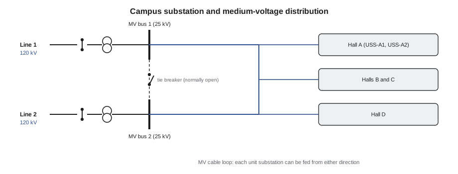
From the substation, medium-voltage cables run underground to unit substations beside each building. Each unit substation has medium-voltage switches, a transformer that steps the voltage down to 600 V, and the low-voltage main breaker. Hall A has two unit substations, USS-A1 and USS-A2, one for each side of its 2N distribution. The medium-voltage cables are laid in a loop, so each unit substation can be fed from either direction if a cable fails.
Getting a connection of this size is one of the hardest parts of building a data centre today. In Quebec, Hydro-Québec allocates large blocks of power to data centres through an approval process, and in 2026 it proposed a separate, higher rate for data centres needing more than 5 MW, to be reviewed by the provincial energy regulator. In Northern Virginia, Dominion Energy has received requests for very large amounts of new data centre capacity, and new campuses there can wait years for transmission upgrades. Stonebridge's operations team does not negotiate these agreements, but they explain why Hall D's power came in stages and why the generator plant was sized for the full campus from the start.
Medium voltage: what technicians need to know
Medium voltage in a data centre usually means anything from about 4 kV to 35 kV. It is distributed through metal-clad switchgear, ring main units and pad-mounted switches. At these voltages, the hazards described in DCT-120 are larger: the shock approach boundaries are wider, arc flash incident energies can be very high, and only medium-voltage-qualified electricians may operate or work on the equipment. A technician entering a medium-voltage room does so only with an escort, stays outside the marked limited approach boundary, and never touches a switch handle or cabinet door.
Medium-voltage switching is done to written switching orders. A switching order lists each operation in sequence, such as opening a particular switch, checking a particular indicator, or applying grounds. Two qualified people carry it out: one reads each step aloud and records it, the other operates. Technicians are often asked to keep the area clear, hold the radio, or record times, but the switching itself belongs to the medium-voltage crew.
Two feeds, one tie: how the substation handles a lost line
The two medium-voltage buses in SUB-1 are joined by a tie breaker that is normally open. In normal operation each utility line and transformer supplies its own bus. If line 1 trips, the protective relays detect the loss of voltage on bus 1, open the bus 1 main breaker and close the tie breaker, so bus 2 now supplies both. This automatic transfer takes a few seconds. During those seconds, the UPS systems carry the IT load from their batteries, and the mechanical plant, which is not on UPS, may stop briefly and restart. The generators do not need to start, because power returns from the other line.
The relay settings deliberately wait a short time before transferring, to ride through faults that clear themselves, such as a lightning strike that causes a brief flashover. Utilities often reclose their own breakers automatically after a fault, sometimes several times. Each attempt shows up downstream as a short interruption or sag. A technician reading the event log after a storm may see a line of events seconds apart; that pattern is the utility's reclosing, not a fault inside the campus.
| Event | What the campus sees | Who rides through it |
|---|---|---|
| Voltage sag of 10 to 30 % for a fraction of a second | Lights flicker; some motor drives may trip | UPS (no transfer to battery is needed for small sags on double conversion); chillers may restart |
| Momentary interruption of under a second, utility reclosing | Loss of one line; UPS on battery briefly | UPS batteries |
| Loss of one utility line | Substation transfers to the other line in seconds | UPS batteries during the transfer |
| Loss of both lines | Total utility outage | UPS batteries, then generators |
| Voltage swell or transient | Surge on the supply | Surge protection and the UPS rectifiers |
Power quality
Utility power is never perfect. Voltage drops briefly when large motors start or when faults occur elsewhere on the network, rises when large loads switch off, and carries harmonics, distortion caused by the electronic loads connected to the network, including data centres themselves. Power quality meters at the incoming lines and switchboards record these events. The figures that matter most to a technician are the voltage on each phase, the frequency, the voltage imbalance between phases and the total harmonic distortion.
The tolerance of IT equipment to voltage disturbances is often shown on a curve first published by the computer industry, known as the CBEMA curve and later revised as the ITIC curve. It shows how far and for how long the voltage can fall or rise before typical IT power supplies may fail. A sag to 70 % of nominal voltage for half a second, for example, lies inside the tolerance region, while a complete loss of voltage for more than about 20 milliseconds lies outside it. The UPS protects the IT load from events outside the curve; the curve is still useful because it explains which events matter for equipment that is not on UPS.
# Check recorded voltage events against a simplified ITIC-style tolerance curve (illustrative)
nominal = 600
events = [  # (start, lowest or highest voltage, duration in seconds)
    ("03:14:07", 468, 0.08), ("03:14:09", 0.0, 0.35), ("11:02:51", 510, 2.5),
    ("16:40:12", 1100, 0.002), ("16:41:30", 390, 0.6),
]
def tolerated(pu, dur):
    if pu > 1.0:                                  # swells
        return pu <= 1.2 or (pu <= 2.0 and dur <= 0.001)
    if dur <= 0.02:
        return True                               # under one cycle: any sag tolerated
    if dur <= 0.5:
        return pu >= 0.70
    if dur <= 10:
        return pu >= 0.80
    return pu >= 0.90
for t, v, dur in events:
    pu = v / nominal
    ok = tolerated(pu, dur)
print(f"{t} {v:6.0f} V {pu * 100:5.1f} % {dur * 1000:7.1f} ms -> {'inside the curve' if ok else 'OUTSIDE: equipment not on UPS may drop'}")03:14:07 468 V 78.0 % 80.0 ms -> inside the curve 03:14:09 0 V 0.0 % 350.0 ms -> OUTSIDE: equipment not on UPS may drop 11:02:51 510 V 85.0 % 2500.0 ms -> inside the curve 16:40:12 1100 V 183.3 % 2.0 ms -> OUTSIDE: equipment not on UPS may drop 16:41:30 390 V 65.0 % 600.0 ms -> OUTSIDE: equipment not on UPS may drop
The two events outside the curve are the momentary interruption at 03:14:09 and the long, deep sag at 16:41:30. Both would have caused equipment without UPS protection to drop. In Hall A on that day, the IT load stayed up, but two of the hall's CRAH fans restarted, which the monitoring system recorded as short alarms. A technician who knows the curve can explain to the shift lead why those alarms happened.
Frequency, voltage limits and the utility's obligations
Utilities hold the voltage within limits set by standards and regulations: in North America, voltage at the service is commonly kept within about plus or minus 5 % of nominal in normal operation, with wider limits allowed briefly. Frequency stays very close to 60 Hz on the large interconnected grids; Quebec's grid is separate from the rest of the eastern North American grid and is connected to it through converter stations, but it also runs at 60 Hz. A sustained drop in frequency is rare and usually means the grid is short of generation, which is serious. Data centre UPS systems tolerate small frequency changes; generators and transfer switches look at frequency as well as voltage when deciding whether utility power is acceptable.
import math
# Read the incoming feed meters and check voltage, imbalance and load (illustrative values)
feeds = {  # line-to-line voltages (V) on the three phases, current per phase (A), power factor
    "Line 1 (MV)": ((25210, 25090, 25150), (182, 179, 185), 0.97),
    "Line 2 (MV)": ((24880, 24410, 24950), (171, 176, 169), 0.96),
}
nominal = 25000
for name, (v, i, pf) in feeds.items():
    v_avg = sum(v) / 3
    imbalance = max(abs(x - v_avg) for x in v) / v_avg * 100
    kw = math.sqrt(3) * v_avg * (sum(i) / 3) * pf / 1000
    dev = (v_avg - nominal) / nominal * 100
    flag = "check" if abs(dev) > 5 or imbalance > 2 else "normal"
print(f"{name}: {v_avg:,.0f} V ({dev:+.1f} %), imbalance {imbalance:.2f} %, load {kw:,.0f} kW -> {flag}")Line 1 (MV): 25,150 V (+0.6 %), imbalance 0.24 %, load 7,690 kW -> normal Line 2 (MV): 24,747 V (-1.0 %), imbalance 1.36 %, load 7,077 kW -> normal
Line 2 shows a phase voltage imbalance just over 1 %, which is within normal limits but worth watching if it grows. Imbalance heats motors and transformers and can be the first sign of a problem on the utility side, such as a failing regulator or a single-phase fault elsewhere.
Utility outages and how the campus responds
When both utility lines are lost, the substation cannot help. The UPS systems carry the IT load from their batteries, every generator on the campus receives a start signal from its transfer controls, and within about ten seconds the generators are running and accepting load. Lesson 8 follows that sequence step by step, and lesson 12 follows a real outage from start to finish. At the utility end, the operations team calls the utility's control centre or large-customer line, records the outage number, and watches for restoration. The campus does not return to utility power the instant it comes back; the transfer controls wait to be sure the utility is stable.
Outages are recorded carefully, because they affect the service-level agreements with customers, the generator run hours allowed by environmental permits, and the reliability history Stonebridge reports. In Quebec, most outages come from storms, especially freezing rain, which loads lines with ice; the 1998 ice storm left parts of the Montérégie region around Beauharnois without power for weeks. Long outages like those are exactly why the generator fuel supply is planned for days rather than hours.
The technician's checks at the utility interface
- On the daily round, read the incoming line meters in the main electrical room display: voltage on each phase, current, power and power factor, and any active alarms.
- Check the substation and medium-voltage room doors are closed and locked and the rooms are dry, without entering unless authorized.
- After any power event, note the time, what the monitoring system shows, and which systems alarmed, before the details are lost.
- Never reset a tripped protective relay or breaker. A trip is evidence; resetting it is for the medium-voltage crew after investigation.
- If utility workers arrive on site, escort them and confirm with the shift lead what work they are doing; they may need access to metering or the substation.
Worked problem
A storm night on the event log
At 03:14 on a stormy night, the monitoring system raises a burst of alarms: UPS-A2 and UPS-B2 on battery, two CRAH restarts, and an event on Line 1. By 03:15 everything is normal again except one message: Line 1 open, tie breaker closed. Jamal is on the night shift with Dmitri.
Show solution
- Jamal opens the event log and lists the events in order: 03:14:07 sag on Line 1 to 78 % for 80 ms; 03:14:09 Line 1 voltage lost; 03:14:12 tie breaker closed; 03:14:12 UPS systems returned from battery; 03:14:20 to 03:14:35 two CRAH units restarted.
- The UPS systems were on battery for about 3 seconds, while the substation transferred to Line 2.
- The generators did not start, because Line 2 was healthy throughout.
- Dmitri calls the utility's large-customer line, which confirms a fault on Line 1 caused by a fallen tree and gives an estimated repair time.
- Jamal checks the UPS battery screens: both systems are recharging normally. He records the event in a ticket with the times and the utility's reference number.
Answer: The campus rode through a lost utility line with only a three-second battery discharge. The campus now runs on one line with no spare, so Dmitri marks the redundancy whiteboard to show that the substation is at N, not N+1, until Line 1 returns. Any planned electrical work that would rely on the second line is postponed.
Common mistakes
MistakeAssuming generators start for every utility event.
InsteadA lost single line is covered by the other line and the tie breaker; generators start only when both are lost.
MistakeResetting a relay or breaker after a trip.
InsteadLeave tripped devices for the qualified crew; the trip records what happened.
MistakeIgnoring short events in the log.
InsteadRecord sags and interruptions; they explain alarms on equipment that is not on UPS.
MistakeEntering a medium-voltage room alone to look.
InsteadEnter only escorted and authorized, and stay outside the limited approach boundary.
MistakeForgetting to update the redundancy status after a feed is lost.
InsteadOne line out means the substation is at N; planned work that needs the second line waits.
Summary and key terms
- The campus is fed by two utility lines into a substation with two transformers and a normally open tie breaker.
- Medium-voltage cables in a loop supply unit substations that step down to the building's low voltage.
- Medium-voltage equipment is operated only by qualified crews under written switching orders.
- Losing one utility line causes a brief UPS discharge; losing both starts the generators.
- Power quality events such as sags, interruptions and imbalance are recorded and can be checked against the ITIC curve.
- Technicians read meters, record events, escort utility crews and update the redundancy status; they never reset trips.
- Substation
- An installation of transformers and switchgear that changes voltage and connects lines.
- Medium voltage
- Voltages from roughly 4 kV to 35 kV, used for distribution around a campus.
- Tie breaker
- A breaker that connects two buses so that one source can supply both.
- Voltage sag
- A short drop in voltage, typically lasting from a few milliseconds to a few seconds.
- ITIC curve
- A curve showing the voltage disturbances typical IT power supplies can tolerate.
- Switching order
- A written sequence of switching operations carried out by qualified people.
Practice problems
Work each problem on paper first, then reveal the answer to check.
Why do the generators not start when one utility line is lost?
Show answer
The other line and the tie breaker restore power within seconds; the UPS batteries cover the gap.
What does a series of short interruptions seconds apart usually show?
Show answer
The utility's automatic reclosing attempts after a fault.
What should a technician do with a tripped relay?
Show answer
Leave it, record it and report it to the qualified crew.
A voltage sag to 75 % lasts 0.3 seconds. Is it inside the simplified tolerance curve in the code?
Show answer
Yes: for up to 0.5 seconds, sags down to 70 % are tolerated.
Lesson quiz · 5 questions
Score 60% or more to complete this lesson.
Create a free account to save your progress, take quizzes and earn a certificate.