
DCE-430 · Lesson 8 of 12 · 28 min
Concrete structures: tilt-up, precast and multi-storey floors
Concrete appears throughout a data centre: in slabs on grade and foundations (Lesson 3), in the exterior walls of many buildings, in precast components, and in the heavy suspended floors of multi-storey data halls. Concrete is strong in compression, weak in tension, durable, fire resistant and massive, which suits the security, fire and acoustic needs of critical facilities. This lesson covers the concrete systems used above the foundations: tilt-up and precast wall panels, precast frames and floors, cast-in-place and post-tensioned suspended slabs for multi-storey data centres, the punching shear problem at columns, and the practical questions of cracking, joints, durability and embodied carbon that decide whether a concrete structure performs well for decades.
Reinforced concrete basics
Concrete's compressive strength \(f'_c\), measured on cylinders at 28 days, is typically 25 to 50 MPa in buildings; its tensile strength is only about a tenth of that, and it cracks when tension exceeds it. Steel reinforcing bars (rebar, typically 400 MPa yield) are placed where tension develops, so that after the concrete cracks the steel carries the tension while the concrete carries compression. Post-tensioning goes further: high-strength steel strands (about 1,860 MPa) in ducts or plastic sheaths are tensioned after the concrete hardens, pre-compressing it so that it cracks less, spans further and deflects less.
In Canada, concrete structures are designed to CSA A23.3, Design of Concrete Structures; concrete materials and construction follow CSA A23.1 and testing CSA A23.2; and precast concrete is produced under CSA A23.4 with plant certification by the Canadian Precast/Prestressed Concrete Institute (CPCI). Loads come from the National Building Code (Lesson 5).
Tilt-up wall panels
In tilt-up construction, wall panels are cast flat on the building's floor slab or on a temporary casting bed, then lifted by crane, tilted to vertical and braced until the roof structure ties them in. Tilt-up suits large single-storey buildings with long, plain walls, which describes most data centres. Panels are typically 180 to 300 mm thick, up to 10 to 15 m tall and 6 to 9 m wide, weighing 30 to 80 tonnes. Advantages include speed, economy for large wall areas, durability, fire resistance, and resistance to wind-borne debris and forced entry, which matters for both natural hazards (Lesson 11) and physical security.
Panels are designed for several stages, and the lifting stage often governs:
- Lifting: the panel is picked up from flat by inserts cast into it, and bending stresses during tilting must stay below the cracking strength, which sets the insert layout and minimum concrete strength at lift (often 15 to 20 MPa).
- Temporary bracing: diagonal pipe braces anchored to the slab hold the panel against wind until the roof diaphragm is connected; brace failures in high winds during construction have caused fatalities, so bracing is engineered.
- In service: the panel acts as a tall, slender wall carrying roof loads eccentrically and bending under wind, with second-order (P-delta) effects; it also acts as a shear wall carrying lateral loads in its plane (Lesson 6).
- Connections between panels, to the roof diaphragm and to the foundation must resist out-of-plane and in-plane forces. In seismic regions, wall-to-roof anchorage is critical: earthquakes in California in 1971 and 1994 pulled heavy concrete walls away from flexible roofs, leading to much stronger anchorage requirements.
Worked problem
Weight and crane for a tilt-up panel
A tilt-up panel is 12 m tall, 7.5 m wide and 250 mm thick, with a door opening 3 m × 4 m. Concrete weighs 24 kN/m³. What does it weigh, and why does the crane capacity need a margin beyond this?
Show solution
- Gross volume: \(12 \times 7.5 \times 0.25 = 22.5\) m³; opening: \(3 \times 4 \times 0.25 = 3.0\) m³; net 19.5 m³.
- Weight: \(19.5 \times 24 = 468\) kN, about 48 tonnes.
- Suction to the casting bed when breaking the panel free can add 10 to 30% momentarily, and the rigging, spreader beams and radius reduce the crane's rated capacity.
Answer: About 48 tonnes. With an allowance for suction and rigging, and the crane working at the radius needed to reach the panel, a crane of 200 to 300 tonnes nominal capacity is typical for such panels, which is why crane selection and ground bearing for the crane pads are planned with the panel layout (Lesson 9 covers lifting).
Precast concrete
Precast elements are cast in a factory under controlled conditions and delivered to site: insulated sandwich wall panels (two concrete layers with insulation between, linked by non-conductive ties), columns, beams, double-tee and hollow-core floor and roof units, stairs and even complete rooms such as electrical buildings. Precast offers high quality, fast erection in any weather and good finishes; prestressing in the factory (pretensioning strands before casting) allows long spans with shallow depths, such as double tees spanning 18 m or more. Limitations include transport size (Lesson 9), the need for many connections, and the joints between elements, which must be sealed against air and water. Precast frames are attractive for multi-storey data centres and for the robust, secure exterior walls of single-storey ones.
Multi-storey data centre floors
Where land is scarce or expensive, data centres are built with two to more than ten storeys of data halls. The suspended floors are among the most heavily loaded floors in any building type: specified live loads of 12 to 20 kPa for racks and equipment, more in battery and transformer rooms, plus superimposed dead loads for services, compared with 2.4 to 4.8 kPa for offices. They must also be stiff (deflection and vibration), allow penetrations for services, and provide fire separation between floors. Common systems:
- Flat plates and flat slabs: uniform-thickness two-way slabs supported directly on columns, sometimes with thickened drop panels or column capitals. They give a flat soffit for easy service routing and minimum storey height.
- Post-tensioned flat plates: thinner and longer-spanning than reinforced flat plates, with less cracking and deflection; widely used in multi-storey data centres. Coring through post-tensioned slabs later is risky because cutting a tendon can be dangerous and costly, so penetrations must be planned and tendons located before drilling.
- One-way slabs on beams or composite steel deck on steel beams: longer column-free spans and lighter weight, at the cost of deeper structure and reduced clear height.
- Precast double tees or hollow core with a cast-in-place topping: fast construction and long spans.
Punching shear
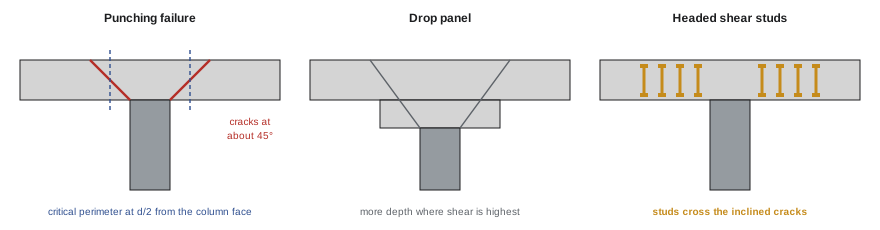
The critical check for flat plates carrying heavy loads is punching shear: the column can push through the slab along a truncated cone of concrete around it, a sudden, brittle failure that has caused progressive collapses of flat-plate buildings when one connection failed and overloaded its neighbours. Codes check the factored shear stress on a critical perimeter at a distance of about half the effective depth \(d/2\) from the column face against a resistance proportional to \(\sqrt{f'_c}\):
import numpy as np

# Punching shear at an interior column of a flat slab supporting a heavy data hall floor (simplified CSA A23.3 approach)
fc = 35.0                         # concrete strength, MPa
phic, lam = 0.65, 1.0
c = 600.0                         # square column size, mm
span = 9.0                        # m, both directions
live, sdl = 15.0, 2.5             # kPa: rack and equipment live load, superimposed dead load
for h in (250, 300, 350):
    d = h - 40                    # effective depth, mm
    sw = 24.0 * h / 1000          # self-weight, kPa
    wf = 1.25 * (sw + sdl) + 1.5 * live
    b0 = 4 * (c + d)              # critical perimeter at d/2 from the column face, mm
    area_inside = ((c + d) / 1000) ** 2
    Vf = wf * (span * span - area_inside)                 # kN
    vf = Vf * 1000 / (b0 * d)                             # MPa (ignores unbalanced moment transfer)
    vc = 0.38 * lam * phic * np.sqrt(fc)                  # MPa
    status = "OK" if vf <= vc else "fails: needs drop panel, column capital or shear reinforcement"
    print(f"slab {h} mm: factored load {wf:4.1f} kPa, Vf = {Vf:4.0f} kN, vf = {vf:.2f} MPa vs vc = {vc:.2f} MPa ({status})")
# 300 mm slab with a 3.0 m square drop panel thickening to 550 mm at the column
h, hd, a = 300, 550, 3000.0
sw_avg = 24.0 * (h + (hd - h) * (a / 1000) ** 2 / span ** 2) / 1000
wf = 1.25 * (sw_avg + sdl) + 1.5 * live
for label, dd, side in (("at the column, through the drop panel", hd - 40, c), ("at the edge of the drop panel, through the slab", h - 40, a)):
    b0 = 4 * (side + dd)
    Vf = wf * (span * span - ((side + dd) / 1000) ** 2)
    vf = Vf * 1000 / (b0 * dd)
    result = "OK" if vf <= vc else "fails"
    print(f"drop panel design, {label}: vf = {vf:.2f} MPa vs vc = {vc:.2f} MPa ({result})")
# Headed shear stud reinforcement raises the maximum factored shear stress to about 0.75 lambda phic sqrt(fc)
vmax = 0.75 * lam * phic * np.sqrt(fc)
for h in (300, 350):
    d = h - 40
    wf = 1.25 * (24.0 * h / 1000 + sdl) + 1.5 * live
    vf = wf * (span * span - ((c + d) / 1000) ** 2) * 1000 / (4 * (c + d) * d)
    result = "OK" if vf <= vmax else "still too high"
print(f"{h} mm slab with headed shear studs: vf = {vf:.2f} MPa vs upper limit {vmax:.2f} MPa ({result})")slab 250 mm: factored load 33.1 kPa, Vf = 2661 kN, vf = 3.91 MPa vs vc = 1.46 MPa (fails: needs drop panel, column capital or shear reinforcement) slab 300 mm: factored load 34.6 kPa, Vf = 2779 kN, vf = 3.11 MPa vs vc = 1.46 MPa (fails: needs drop panel, column capital or shear reinforcement) slab 350 mm: factored load 36.1 kPa, Vf = 2896 kN, vf = 2.57 MPa vs vc = 1.46 MPa (fails: needs drop panel, column capital or shear reinforcement) drop panel design, at the column, through the drop panel: vf = 1.25 MPa vs vc = 1.46 MPa (OK) drop panel design, at the edge of the drop panel, through the slab: vf = 0.74 MPa vs vc = 1.46 MPa (OK) 300 mm slab with headed shear studs: vf = 3.11 MPa vs upper limit 2.88 MPa (still too high) 350 mm slab with headed shear studs: vf = 2.57 MPa vs upper limit 2.88 MPa (OK)
With 15 kPa live load on a 9 m grid, even a 350 mm flat plate fails in punching. Thickening the slab locally with a drop panel solves the problem with modest extra concrete, and headed shear studs around the column let a 350 mm slab work without a drop. The calculation shown ignores the transfer of unbalanced moment between slab and column, which increases the shear stress at edge and corner columns and under uneven loading, so real designs have even less margin. Punching shear is a strong reason for data centre floors to use drop panels, column capitals, shear reinforcement or beams, and for owners to resist heavier loads on floors not designed for them.
Comparing floor systems
import numpy as np

# Concrete floor options for a multi-storey data hall: thickness, self-weight and embodied carbon per square metre
live, sdl = 15.0, 2.5
co2_concrete = 300.0                 # kg CO2e per m3 for a typical 35 MPa mix
co2_rebar, co2_strand = 1.2, 2.0     # kg CO2e per kg of reinforcing steel and post-tensioning strand
options = [
    # name, span (m), thickness (mm), rebar kg/m2, strand kg/m2
    ("reinforced flat plate with drop panels", 9.0, 300, 32, 0),
    ("post-tensioned flat plate", 9.0, 250, 14, 6),
    ("post-tensioned flat plate", 12.0, 300, 18, 9),
    ("one-way slab on beams at 3 m centres", 3.0, 150, 14, 0),
]
for name, span, h, rebar, strand in options:
    sw = 24.0 * h / 1000
    extra = 0.12 if "beams" in name else 0.04 if "drop" in name else 0.0   # beams or drops as equivalent extra depth (m)
    vol = h / 1000 + extra
    co2 = vol * co2_concrete + rebar * co2_rebar + strand * co2_strand
print(f"{name}, {span:.0f} m span: {h} mm slab, span/depth {span * 1000 / h:4.0f}, self-weight {24 * vol:4.1f} kPa vs live {live} kPa, about {co2:3.0f} kg CO2e/m2")reinforced flat plate with drop panels, 9 m span: 300 mm slab, span/depth 30, self-weight 8.2 kPa vs live 15.0 kPa, about 140 kg CO2e/m2 post-tensioned flat plate, 9 m span: 250 mm slab, span/depth 36, self-weight 6.0 kPa vs live 15.0 kPa, about 104 kg CO2e/m2 post-tensioned flat plate, 12 m span: 300 mm slab, span/depth 40, self-weight 7.2 kPa vs live 15.0 kPa, about 130 kg CO2e/m2 one-way slab on beams at 3 m centres, 3 m span: 150 mm slab, span/depth 20, self-weight 6.5 kPa vs live 15.0 kPa, about 98 kg CO2e/m2
Post-tensioning saves concrete and reinforcement, reducing self-weight and embodied carbon by roughly a quarter compared with a reinforced flat plate on the same grid, and allows longer spans for the same depth, though punching shear at the columns still needs attention. Beam-and-slab systems use less slab concrete but add beams that reduce clear height and complicate service routing. The numbers here are indicative only: actual quantities depend on loads, spans, fire ratings and local practice, and should come from design. Self-weight matters because it adds to column and foundation loads, which accumulate down a multi-storey building, and to seismic mass (Lesson 7).
Cracking, shrinkage and joints
Concrete shrinks as it dries, by about 0.04 to 0.08% of its length over months, and moves with temperature. Restrained shrinkage causes cracking, which is unsightly, can let water reach reinforcement, and in data centres can cause dust and problems for rolling equipment and floor coatings. Control measures include:
- Control (contraction) joints sawn or formed at regular spacings, typically 24 to 36 times the slab thickness for slabs on grade, so that cracks form in straight lines at the joints.
- Construction joints between pours, detailed with dowels to transfer load across them.
- Adequate reinforcement to keep cracks narrow where restraint is unavoidable, and post-tensioning to keep slabs in compression.
- Mix design with lower water content, shrinkage-reducing admixtures and well-graded aggregates.
- Curing: keeping concrete moist for at least seven days, with wet curing, curing compounds or covers, which greatly reduces early cracking and improves surface durability.
Joints in floors where equipment rolls, such as server lifts and pallet jacks, should be filled with semi-rigid joint filler and have edges protected so they do not spall.
Durability
Concrete structures should last 50 to 100 years, which depends on resisting the deterioration mechanisms of their exposure:
- Corrosion of reinforcement caused by chlorides from de-icing salts or by carbonation: controlled by adequate concrete cover (typically 40 to 60 mm outdoors), low water-cement ratios, and, in severe exposures, epoxy-coated or galvanized bars or corrosion-inhibiting admixtures.
- Freeze-thaw damage of saturated concrete in cold climates such as most of Canada: controlled by air entrainment (5 to 8% air), which provides tiny voids for water to expand into.
- Sulphate attack from certain soils and groundwater: controlled by sulphate-resistant cements.
- Alkali-aggregate reaction with some aggregates: controlled by testing aggregates and using supplementary cementing materials.
Canadian and US standards assign exposure classes, such as CSA A23.1 classes C-1 for structurally reinforced concrete exposed to chlorides with freezing and thawing, that set maximum water-cement ratio, minimum strength, air content and cover. Outdoor slabs at generator yards and loading docks, which see de-icing salts and fuel spills, need the most demanding classes.
Embodied carbon in concrete
Cement production releases about 0.8 to 0.9 tonnes of CO₂ per tonne of clinker, making concrete the largest source of embodied carbon in most data centre structures (Lesson 5 introduced embodied carbon). Reductions come from structural efficiency (post-tensioning, avoiding over-thick slabs and over-designed foundations), lower-carbon cements such as Portland-limestone cement (Type GUL in Canada), replacing part of the cement with supplementary cementing materials such as slag and fly ash, specifying strength at 56 rather than 28 days so that slower-gaining low-carbon mixes can be used, and emerging technologies such as carbon mineralization during mixing. Environmental product declarations (EPDs) from concrete suppliers quantify the carbon of each mix, and many owners now set carbon limits in their specifications. Public procurement in Canada increasingly requires low-carbon concrete and EPDs on federal projects.
Common mistakes
MistakeDesigning tilt-up panels only for in-service loads.
InsteadCheck lifting, temporary bracing and in-service stages.
MistakeWeak wall-to-roof connections in seismic regions.
InsteadProvide strong, ductile anchorage between heavy walls and the diaphragm.
MistakeAssuming a thicker flat plate always solves heavy loads.
InsteadCheck punching shear; use drop panels, capitals or shear studs.
MistakeCoring post-tensioned slabs without locating tendons.
InsteadScan for tendons and plan penetrations before drilling.
MistakeSkipping curing and joint layout to save time.
InsteadCure properly and place control joints to manage shrinkage cracking.
Summary and key terms
- Concrete is strong in compression, weak in tension; reinforcement and post-tensioning handle tension and cracking.
- Tilt-up panels suit large single-storey walls but must be designed for lifting, bracing and service, with strong roof connections.
- Precast elements give quality and speed; joints and transport must be planned.
- Multi-storey data hall floors carry 12 to 20 kPa and use flat plates, post-tensioned slabs, beams or precast units.
- Punching shear governs heavily loaded flat plates; drop panels, capitals and shear studs resolve it.
- Joints, curing and mix design control shrinkage cracking; exposure classes govern durability.
- Efficient structures, low-carbon cements and EPDs reduce concrete's embodied carbon.
- Tilt-up
- Wall panels cast flat on site and tilted into place.
- Precast concrete
- Concrete elements cast in a factory and erected on site.
- Post-tensioning
- Tensioning strands after concrete hardens to pre-compress it.
- Flat plate
- A two-way slab supported directly on columns without beams.
- Drop panel
- A local thickening of a slab around a column.
- Punching shear
- Failure of a slab around a column along a cone-shaped surface.
- Critical perimeter
- The perimeter at about d/2 from a column face used for punching checks.
- Control joint
- A planned weakened line where shrinkage cracks form.
- Air entrainment
- Microscopic air voids that protect concrete from freeze-thaw damage.
- Exposure class
- A durability category setting concrete mix and cover requirements.
Practice problems
Work each problem on paper first, then reveal the answer to check.
Weight of a 10 m × 6 m × 0.22 m tilt-up panel at 24 kN/m³?
Show answer
\(13.2 \times 24 = 317\) kN, about 32 t.
Which construction stage often governs tilt-up panel design?
Show answer
Lifting.
Typical data hall floor live load?
Show answer
12 to 20 kPa.
Critical perimeter for a 500 mm square column with d = 300 mm?
Show answer
\(4 \times 800 = 3{,}200\) mm.
Approximate v_c for f'_c = 30 MPa (λ = 1, φ_c = 0.65)?
Show answer
\(0.38 \times 0.65 \times 5.48 = 1.35\) MPa.
Name two remedies for punching shear.
Show answer
Drop panels, column capitals, shear studs, thicker slab.
Why is coring a PT slab risky?
Show answer
Cutting a tendon is dangerous and weakens the slab.
Control joint spacing for a 200 mm slab on grade at 30 times thickness?
Show answer
6 m.
What protects concrete from freeze-thaw damage?
Show answer
Air entrainment.
Name two ways to cut concrete's embodied carbon.
Show answer
Portland-limestone cement, slag or fly ash, efficient design, 56-day strength.
Lesson quiz · 5 questions
Score 60% or more to complete this lesson.
Create a free account to save your progress, take quizzes and earn a certificate.