
DCE-430 · Lesson 5 of 12 · 32 min
Structural systems and roof equipment loads
The structure of a data centre has an unusual job. It must enclose very large, column-free or regularly gridded halls; carry heavy equipment on floors, roofs and from ceilings; resist wind, snow and earthquakes to a higher standard than most buildings; and be built fast, often in repeated phases, by owners racing to bring capacity online. This lesson covers the main structural systems used for data centres, how dead, live, equipment and hanging loads are combined, the design of roofs carrying mechanical equipment, the support of overhead services including liquid cooling piping, floor vibration, and the growing attention to embodied carbon in structural materials.
Structural systems
Most data centres use one of a few structural forms:
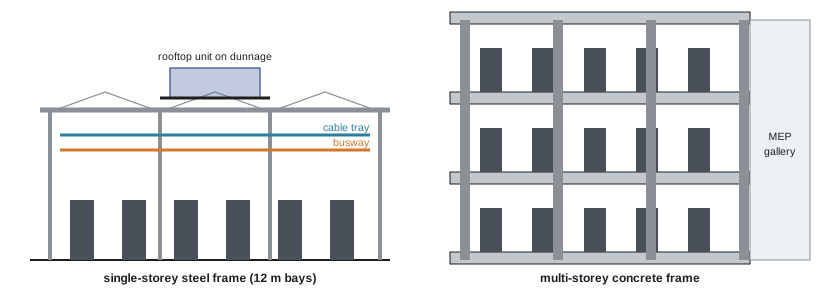
- Single-storey steel frame: steel columns on a grid (commonly 9 to 18 m), with steel joists or trusses and steel deck supporting the roof, and walls of insulated metal panels or precast concrete. Fast, economical and adaptable; the dominant form for large campuses with available land.
- Precast or tilt-up concrete: concrete wall panels cast on site (tilt-up) or in a factory (precast) form the exterior walls and often act as shear walls, with a steel roof structure. Robust against wind-borne debris, fire and security threats.
- Multi-storey concrete or steel: two to five or more storeys of data halls, with heavy suspended floor slabs (often post-tensioned concrete or composite steel deck) on a column grid. Used where land is scarce or expensive, in cities and around constrained power sites. Floor loads, vibration and service distribution between levels govern the design.
- Pre-engineered and modular buildings: factory-built frames or modules assembled on site (Lesson 9).
Clear heights inside data halls have grown to accommodate hot aisle containment, overhead busways, cable trays at several levels, sprinkler piping and liquid cooling distribution: 5 to 7 m to the underside of structure is common, with more in high-density AI halls. Grid spacing is coordinated with rack rows (a rack row pitch of 2.4 to 3.6 m fits neatly into 9 to 18 m bays), so columns do not interrupt rows.
Loads and load combinations
Structural design considers several categories of load:
- Dead load (D): the weight of the structure, cladding, roofing, fixed services and permanent equipment.
- Live load (L): occupancy and movable contents, including racks (Lesson 3).
- Equipment loads: often treated as dead load when permanent and precisely known, or as live load when they may change; owners usually specify allowances for future equipment.
- Hanging (collateral) loads: busways, cable trays, ductwork, sprinkler and cooling pipes, containment and lighting hung from the roof or floor above.
- Snow (S), wind (W) and earthquake (E) loads (Lesson 7).
- Rain and ponding loads on roofs.
These loads are combined using load factors that reflect their uncertainty and the low probability of several maximum loads occurring together:
| Case | Principal load | Companion loads |
|---|---|---|
| 1 | 1.4D | — |
| 2 | 1.25D + 1.5L | + 1.0S or 0.4W |
| 3 | 1.25D + 1.5S | + 1.0L or 0.4W |
| 4 | 1.25D + 1.4W | + 0.5L or 0.5S |
| 5 | 1.0D + 1.0E | + 0.5L + 0.25S |
Worked problem
Factored roof load
A roof area carries dead load 1.0 kPa (deck, roofing, joists), hanging services 0.8 kPa (treated as dead), roof live load is not concurrent with snow, and specified snow load 2.0 kPa. Find the governing factored load for gravity.
Show solution
- D = 1.8 kPa. Case 1: \(1.4 \times 1.8 = 2.52\) kPa.
- Case 3: \(1.25 \times 1.8 + 1.5 \times 2.0 = 2.25 + 3.0 = 5.25\) kPa.
Answer: The snow case governs at 5.25 kPa. Hanging services account for almost half the dead load, which is typical of data halls and is why owners specify collateral load allowances for the roof structure.
Roof-mounted equipment
Many data centres place cooling equipment on the roof: air-cooled chillers, dry coolers, condensers, air handling units and exhaust fans. Each unit may weigh 5 to 40 tonnes in operation, with water-cooled units heavier when full. Roof-mounted equipment affects the structure in several ways:
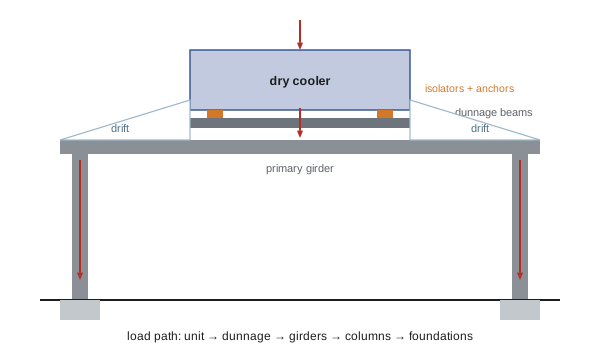
- Concentrated gravity loads, carried by dunnage steel (secondary beams or frames) that spreads the load to primary girders and columns rather than to the light roof joists.
- Snow drifts that form against and around the equipment (Lesson 7), adding significant load.
- Wind loads on the equipment itself, and uplift and overturning that must be resisted by anchorage.
- Seismic forces on the equipment, which are amplified with height in the building and must be resisted by anchors and the supporting structure (Lesson 7).
- Vibration from fans and compressors, which requires isolators and stiff supports.
- Maintenance access, walkways, guardrails and crane access for replacement.
Placing equipment on grade beside the building avoids most of these issues and simplifies maintenance, at the cost of land; placing it on the roof saves land and shortens piping. Owners decide based on site size and density; many AI data centres now place heat rejection on grade or in dedicated mechanical yards because of the weight and size of the equipment.
Worked problem
Dunnage beam for a rooftop unit
A 24-tonne dry cooler sits on two parallel dunnage beams, each spanning 12 m between girders, with the unit's weight applied as two equal point loads per beam at the third points. Find the maximum moment in each beam (ignoring self-weight).
Show solution
- Unit weight: \(24 \times 9.81 = 235\) kN; per beam 117.7 kN; two point loads of 58.9 kN.
- For two equal loads \(P\) at the third points of span \(L\): \(M_{max} = PL/3 = 58.9 \times 12/3 = 235\) kN·m (service).
- Factored as dead load: \(1.25 \times 235 = 294\) kN·m (with snow as companion load added separately).
Answer: Each dunnage beam must resist about 235 kN·m at service, roughly 280 to 300 kN·m factored before snow drift is added, a substantial steel section (for example a W530 or W21 shape). Equipment supports are often a large share of a data centre roof's steel tonnage.
Ponding and roof drainage
Flat roofs are especially vulnerable to ponding: rainwater that accumulates in a deflected area adds load, which increases deflection, which collects more water. If the roof is too flexible, this feedback leads to collapse. Designers prevent it by providing adequate slope (at least 2% is common), primary and secondary (overflow) drains or scuppers sized for the design rainfall, and members stiff enough that ponding stability is assured. The secondary drainage system must work if primary drains are blocked, because the rain load is calculated assuming the water rises to the level of the overflow. Large data centre roofs, sometimes over 30,000 m² on a single building, need careful layout of drains, crickets and slopes.
Worked problem
Rain load on a blocked roof
A roof's primary drains are blocked; water rises to the overflow scuppers, which are 75 mm above the roof surface at the drain, with a further 50 mm hydraulic head needed to discharge the design flow. What is the rain load at the drain?
Show solution
- Depth \(= 75 + 50 = 125\) mm of water.
- Load \(= 0.125 \times 9.81 = 1.23\) kPa (about 26 psf).
Answer: About 1.2 kPa, which can exceed the roof live load. If the roof deflects under this water, the depth increases further, so ponding checks use the deflected shape.
Supporting overhead services
In slab-on-grade data halls without raised floors, almost everything is hung from above: busways, several tiers of cable tray, containment ceilings, lighting, fire detection and sprinklers, and increasingly large liquid cooling pipes and manifolds. These collateral loads can reach 1.5 to 3 kPa averaged over the hall, with heavy concentrations along rack rows. Structural engineers coordinate a support system, often a grid of hanging steel (unistrut, angles or purpose-made frames) from the roof structure, and specify where heavy point loads may be attached. Liquid cooling piping is particularly heavy when full: a 300 mm steel pipe full of water weighs about 140 kg per metre.
Worked problem
Weight of a full cooling pipe
A liquid cooling loop has a supply and return pipe, each DN 250 (inside diameter 255 mm, steel weight 60 kg/m), full of water, plus 25 kg/m of insulation and supports. What load per metre do they impose on the hanger system?
Show solution
- Water per pipe: \(\pi \times 0.1275^2 \times 1000 = 51\) kg/m.
- Per pipe: \(60 + 51 = 111\) kg/m; two pipes: 222 kg/m; with insulation and supports: 247 kg/m.
- Load: \(247 \times 9.81 = 2.4\) kN/m.
Answer: About 2.4 kN/m, equivalent to hanging a small car every 5 m. Main liquid cooling pipes in AI data halls are often supported from dedicated steel or routed at floor level or in service corridors to avoid overloading the roof structure.
Floor vibration in multi-storey data centres
Suspended floors in multi-storey data halls must be stiff enough that footfall, equipment and rack movement do not cause vibrations that disturb people or sensitive equipment. Vibration criteria are expressed through the floor's natural frequency and response to walking; heavy concrete floors with frequencies above about 8 to 10 Hz generally perform well. Long-span lightweight floors are more susceptible. Mechanical equipment on upper floors needs isolation and, where large, dedicated stiff structure.
Embodied carbon
Concrete and steel production are major sources of greenhouse gas emissions, and a large data centre contains tens of thousands of tonnes of concrete and many thousands of tonnes of steel. As operators pursue carbon goals (DCE-460), they increasingly track embodied carbon (the emissions from producing and building with materials) through environmental product declarations, and reduce it with:
- Lower-carbon concrete using supplementary cementitious materials (fly ash, slag, calcined clay) and Portland-limestone cement, and optimizing strength and quantity.
- Steel with high recycled content made in electric arc furnaces.
- Efficient structural design: right-sizing members, avoiding overly conservative loads, and reusing standard designs.
- Mass timber for some building elements, such as office and support areas, and increasingly for data hall structures, where fire and load requirements allow.
Worked problem
Embodied carbon of a slab
A 20,000 m² data hall slab is 250 mm thick. Compare the embodied carbon of conventional concrete at 350 kg CO₂e/m³ and a low-carbon mix at 220 kg CO₂e/m³.
Show solution
- Volume: \(20{,}000 \times 0.25 = 5000\) m³.
- Conventional: \(5000 \times 350 = 1750\) t CO₂e. Low-carbon: \(5000 \times 220 = 1100\) t CO₂e.
- Saving: 650 t CO₂e.
Answer: The low-carbon mix saves about 650 t CO₂e on the slab alone, roughly the annual emissions from 150 cars. Reductions like this are often achievable at little or no cost, though mixes with high cement replacement gain strength more slowly, which can affect construction schedules.
Lesson 6 develops the design of steel members, joists, diaphragms and connections, and Lesson 8 the concrete structures used in walls and multi-storey floors.
Common mistakes
MistakeUnderestimating hanging (collateral) loads.
InsteadSpecify allowances for busways, trays, containment and full cooling pipes.
MistakePlacing heavy rooftop units directly on light roof joists.
InsteadUse dunnage steel to carry loads to primary members.
MistakeIgnoring snow drift around rooftop equipment.
InsteadInclude drift loads against equipment and parapets (Lesson 7).
MistakeRelying on primary drains alone.
InsteadProvide secondary overflow drains and check ponding stability.
MistakeIgnoring embodied carbon in material choices.
InsteadSpecify low-carbon concrete and recycled steel and right-size members.
Summary and key terms
- Single-storey steel frames dominate; tilt-up, precast and multi-storey concrete or steel are also used.
- Clear heights of 5 to 7 m and grids aligned with rack rows suit overhead services.
- NBC combines loads with principal and companion factors such as 1.25D + 1.5L + 1.0S.
- Rooftop equipment requires dunnage, anchorage and checks for drift, wind, seismic and vibration.
- Ponding and blocked-drain rain loads govern flat roof design.
- Overhead services, especially full cooling pipes, impose heavy collateral loads.
- Multi-storey floors must meet vibration criteria.
- Low-carbon concrete, recycled steel and efficient design reduce embodied carbon.
- Dead load
- The weight of the structure and permanent elements.
- Collateral load
- The weight of services and equipment hung from or attached to the structure.
- Load combination
- A sum of factored loads checked in design.
- Dunnage
- Secondary steel supporting equipment on a roof.
- Ponding
- Progressive accumulation of water in a deflecting roof.
- Secondary drainage
- Overflow drains or scuppers that work when primary drains are blocked.
- Tilt-up construction
- Concrete wall panels cast on site and lifted into place.
- Embodied carbon
- Emissions from producing materials and constructing a building.
- Supplementary cementitious materials
- Materials such as slag and fly ash that replace part of the cement.
Practice problems
Work each problem on paper first, then reveal the answer to check.
Why are column grids coordinated with rack rows?
Show answer
So columns do not interrupt rows and containment.
D = 1.5 kPa, L = 12 kPa. Factored load for case 2 (ignore companions)?
Show answer
1.25 × 1.5 + 1.5 × 12 = 19.9 kPa.
A 30 t unit sits on two beams spanning 10 m, loads at third points. Service moment per beam?
Show answer
P = 73.6 kN; M = PL/3 = 245 kN·m.
Name four ways rooftop equipment loads the structure.
Show answer
Gravity point loads, snow drift, wind and uplift, seismic forces, vibration.
Rain load for 100 mm of water?
Show answer
0.98 kPa (about 20 psf).
Why must secondary drains be provided?
Show answer
If primary drains clog, water would rise without limit and overload the roof.
Weight per metre of water in a pipe of 200 mm inside diameter?
Show answer
π × 0.1² × 1000 = 31.4 kg/m.
Why are heavy cooling pipes sometimes routed at floor level?
Show answer
To avoid overloading roof structure and simplify supports and leak management.
Embodied carbon of 3000 m³ of concrete at 300 kg CO₂e/m³?
Show answer
900 t CO₂e.
Give two ways to reduce embodied carbon in concrete.
Show answer
Replace cement with slag, fly ash or calcined clay; use Portland-limestone cement; reduce volume and strength where possible.
Lesson quiz · 5 questions
Score 60% or more to complete this lesson.
Create a free account to save your progress, take quizzes and earn a certificate.