
DCE-430 · Lesson 2 of 12 · 31 min
Site utilities and underground infrastructure
Below the graded pads and roads of Lesson 1 lies a dense network of buried services: fire water mains and hydrants, domestic water, cooling makeup water, sanitary sewers, storm drains, fuel lines, electrical duct banks from the substation to each building, and fibre routes to the outside world. On a large campus these run for kilometres and cross each other hundreds of times. They are expensive to install, very expensive to move once buildings and paving are in place, and some of them, such as the electrical duct banks and fibre routes, carry the services the facility exists to deliver. This lesson covers how site utilities are planned, sized and protected: water supply for fire fighting and cooling, sanitary and process drainage, fuel systems, electrical and telecommunications duct banks, and the coordination that keeps them from conflicting.
Planning the utility corridor
Site utilities are usually grouped in planned corridors alongside roads, so that they can be found, maintained and extended without disturbing buildings. Good practice includes:
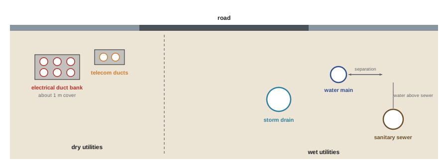
- Separating "wet" utilities (water, sewer, storm, fuel) from "dry" ones (electrical, telecommunications) horizontally and vertically, so that a leak or excavation for one does not damage the other.
- Following minimum separations set by regulators: water mains are typically kept at least 2.5 to 3 m horizontally from sanitary sewers and above them where they cross, to prevent contamination.
- Providing diverse routes for critical services. Two electrical feeds from separate substations or transformers, and two or more fibre entrances, should follow physically separate paths into the building, typically at least 20 m apart, so that a single excavation accident cannot cut both.
- Recording everything in an as-built utility model with depths and coordinates, and marking buried services with warning tape and tracer wire.
- Leaving spare capacity: empty ducts, larger mains and space in corridors for future phases, because campuses usually grow.
Before design, existing utilities are located through records and a subsurface utility engineering (SUE) investigation, which classifies the reliability of utility information from quality level D (records only) to quality level A (exposed by test pits and surveyed). Utility strikes during construction are a leading cause of delay and injury.
Fire water supply
Data centres are sprinklered buildings with high-value contents, so the fire water supply must deliver both the sprinkler demand and the hose and hydrant demand for fire fighters, at adequate pressure, for a required duration. The required fire flow depends on the building's size, construction, occupancy and sprinkler protection.
In Canada, municipal water utilities and fire services commonly use the Fire Underwriters Survey water supply guide to set required fire flows, and the National Fire Code and the building code govern hydrants, fire department connections and private fire mains, with sprinkler systems designed to NFPA 13 and private mains to NFPA 24 as referenced standards. Typical required flows for large sprinklered industrial buildings are 100 to 200 L/s for 2 to 3 hours.
The minimum residual pressure in the main during fire flow is usually 140 kPa (20 psi), so that hydrants remain usable and contamination cannot be drawn into the system. Friction loss in pipes is commonly calculated with the Hazen-Williams formula:
where \(h_f\) is head loss (m), \(L\) the length (m), \(Q\) the flow (m³/s), \(D\) the internal diameter (m) and \(C\) a roughness coefficient (about 130 to 150 for ductile iron and PVC). The strong dependence on diameter, the fifth power approximately, means that one size larger pipe dramatically reduces losses.
import numpy as np

# Fire water main: Hazen-Williams head loss and residual pressure at the most remote hydrant
def hw_loss(Q_Ls, D_mm, L_m, C=130):
    Q = Q_Ls / 1000                                       # m3/s
    D = D_mm / 1000
    return 10.67 * L_m * Q ** 1.852 / (C ** 1.852 * D ** 4.8704)   # head loss in metres of water

static_kPa = 480.0            # municipal static pressure at the site connection
L = 650.0                     # length of loop to the remote hydrant (one path), m
for D in (150, 200, 250, 300):
    for Q in (95, 150, 250):  # fire flow, L/s (about 1,500, 2,400 and 4,000 US gpm)
        h = hw_loss(Q, D, L)
        residual = static_kPa - 9.81 * h - 9.81 * 3.0              # minus 3 m elevation rise
        if residual >= 140:
            result = f"residual {residual:4.0f} kPa, OK"
        elif residual > 0:
            result = f"residual {residual:4.0f} kPa, below the 140 kPa minimum"
        else:
            result = "cannot deliver this flow (pressure would fall below zero)"
        print(f"main {D} mm, fire flow {Q:3d} L/s: friction loss {h:6.1f} m; {result}")
# A looped main fed from both ends splits the flow, roughly halving the flow in each path
h_loop = hw_loss(125, 250, L)
print(f"looped 250 mm main, 250 L/s split in two paths: residual {static_kPa - 9.81 * h_loop - 9.81 * 3.0:.0f} kPa")main 150 mm, fire flow 95 L/s: friction loss 111.1 m; cannot deliver this flow (pressure would fall below zero) main 150 mm, fire flow 150 L/s: friction loss 258.8 m; cannot deliver this flow (pressure would fall below zero) main 150 mm, fire flow 250 L/s: friction loss 666.5 m; cannot deliver this flow (pressure would fall below zero) main 200 mm, fire flow 95 L/s: friction loss 27.4 m; residual 182 kPa, OK main 200 mm, fire flow 150 L/s: friction loss 63.7 m; cannot deliver this flow (pressure would fall below zero) main 200 mm, fire flow 250 L/s: friction loss 164.2 m; cannot deliver this flow (pressure would fall below zero) main 250 mm, fire flow 95 L/s: friction loss 9.2 m; residual 360 kPa, OK main 250 mm, fire flow 150 L/s: friction loss 21.5 m; residual 240 kPa, OK main 250 mm, fire flow 250 L/s: friction loss 55.4 m; cannot deliver this flow (pressure would fall below zero) main 300 mm, fire flow 95 L/s: friction loss 3.8 m; residual 413 kPa, OK main 300 mm, fire flow 150 L/s: friction loss 8.8 m; residual 364 kPa, OK main 300 mm, fire flow 250 L/s: friction loss 22.8 m; residual 227 kPa, OK looped 250 mm main, 250 L/s split in two paths: residual 300 kPa
A 200 mm main is adequate for a modest fire flow but cannot deliver 150 L/s 650 m from the connection; a 250 mm main can, but not 250 L/s, unless it is looped so that water reaches the hydrant from both directions. Looping also provides redundancy: a break can be isolated with valves while the rest of the loop stays in service. Where municipal mains cannot supply the required flow and pressure, the site needs fire water storage tanks and fire pumps, typically two electric or one electric and one diesel pump for reliability, sized for the full design duration.
Worked problem
Fire water storage
A site needs 150 L/s for 2 hours for sprinklers and hoses. The municipal connection can provide only 60 L/s reliably. What tank volume is needed to make up the shortfall?
Show solution
- Total demand: \(150 \times 7{,}200 = 1{,}080{,}000\) L \(= 1{,}080\) m³.
- Supply from the municipal connection: \(60 \times 7{,}200 = 432\) m³.
- Storage: \(1{,}080 - 432 = 648\) m³, plus an allowance for unusable volume below the pump suction, typically 10 to 15%.
Answer: About 650 m³ of effective storage, or roughly 750 m³ of tank volume; many designers instead size the tank for the full 1,080 m³ so that fire protection does not depend on the municipal supply at all, which insurers often prefer.
Water for cooling
Data centres that use evaporative cooling, such as cooling towers, evaporative coolers or adiabatic dry coolers, consume large amounts of water at peak conditions. Water leaves the system by evaporation, which does the cooling, and by blowdown, the deliberate discharge of some water to limit the build-up of dissolved minerals. The ratio of mineral concentration in the circulating water to that in the makeup is the cycles of concentration; higher cycles reduce blowdown but require better water treatment.
import numpy as np

# Water for evaporative cooling: evaporation, blowdown and on-site storage for an IT load
IT_MW = 30.0
heat_MW = IT_MW * 1.15                    # heat rejected including mechanical and electrical losses
h_fg = 2.43e6                             # latent heat of evaporation, J/kg, near 30 C
evap_kg_s = heat_MW * 1e6 / h_fg * 0.85   # about 85% of heat rejected by evaporation at design conditions
for coc in (3, 5, 8):                     # cycles of concentration
    blowdown = evap_kg_s / (coc - 1)
    makeup = evap_kg_s + blowdown
    print(f"cycles {coc}: evaporation {evap_kg_s:5.1f} L/s, blowdown {blowdown:4.1f} L/s, makeup {makeup:5.1f} L/s = {makeup * 86.4:6.0f} m3/day at peak")
# Annual use: evaporative cooling only above about 18 C wet-bulb-equivalent; assume 2,000 equivalent full-load hours
makeup5 = evap_kg_s * (1 + 1 / 4)
annual_m3 = makeup5 * 3.6 * 2000
print(f"annual makeup at 5 cycles with 2,000 equivalent hours: {annual_m3:,.0f} m3 ({annual_m3 * 1000 / (IT_MW * 8760 * 1000):.2f} L per kWh of IT energy)")
# Storage to ride through a 48-hour loss of municipal supply at peak
print(f"48-hour storage at peak makeup: {makeup5 * 3.6 * 48:,.0f} m3")cycles 3: evaporation 12.1 L/s, blowdown 6.0 L/s, makeup 18.1 L/s = 1564 m3/day at peak cycles 5: evaporation 12.1 L/s, blowdown 3.0 L/s, makeup 15.1 L/s = 1303 m3/day at peak cycles 8: evaporation 12.1 L/s, blowdown 1.7 L/s, makeup 13.8 L/s = 1192 m3/day at peak annual makeup at 5 cycles with 2,000 equivalent hours: 108,611 m3 (0.41 L per kWh of IT energy) 48-hour storage at peak makeup: 2,607 m3
At peak, a 30 MW facility with evaporative cooling needs about 15 L/s of makeup water, over 1,300 m³ per day, comparable to a town of several thousand people. Annual consumption depends on climate and the hours of evaporative operation; in a cool Canadian climate with economizers, the evaporative hours are few and the water usage effectiveness (WUE) may be 0.2 to 0.5 L/kWh, while in hot, dry climates it can exceed 1.5 L/kWh. The utility planning consequences are significant: the municipal water supply must have capacity for the peak demand, the sewer must accept the blowdown (which contains concentrated minerals and treatment chemicals and may need pre-treatment), and on-site storage is usually provided so that cooling continues through a supply interruption, often for 24 to 72 hours. Many operators now choose closed-loop dry coolers or air-cooled chillers to avoid water use entirely, accepting higher energy use on hot days (DCE-330), or use reclaimed or non-potable water.
Sanitary and process drainage
A data centre has relatively few occupants, so domestic sanitary flows are small, but process discharges can be large: cooling tower blowdown, reverse osmosis reject water, and condensate. Discharges to municipal sewers must meet the municipality's sewer-use bylaw or ordinance, which limits temperature, pH, metals and chemicals, and may require sampling manholes and permits. Oil-water separators are installed downstream of generator yards, fuel unloading areas and transformer containment, and floor drains in generator and fuel rooms connect to them rather than directly to storm or sanitary sewers. Sewers are designed for gravity flow at velocities of at least about 0.6 m/s to keep solids moving, using Manning's equation for pipe capacity, with pumping stations where the terrain does not allow gravity drainage.
Fuel systems
Standby generators (DCE-320) typically store fuel for 24 to 72 hours of full-load operation, so a large campus may hold several hundred thousand litres of diesel. Fuel is stored in belly tanks under each generator, in bulk aboveground or underground tanks with transfer pumps, or both. The civil design must provide:
- Secondary containment: double-walled tanks and piping, or bunded areas holding at least 110% of the largest tank, to contain leaks and spills.
- Fuel unloading areas with containment curbs and spill kits, positioned for safe tanker access and away from building air intakes.
- Leak detection in interstitial spaces and sumps, and overfill protection.
- Separation from buildings, property lines and ignition sources, as required by fire codes.
In Canada, fuel storage tank systems are regulated by the National Fire Code and provincial fire codes, by the CCME Environmental Code of Practice for Aboveground and Underground Storage Tank Systems, and, for systems on federal land or certain federally regulated sites, by the federal Storage Tank Systems for Petroleum Products and Allied Petroleum Products Regulations, which require registration, installation by qualified people and leak detection.
Electrical duct banks
Medium-voltage cables from the substation to each building, and between buildings, usually run underground in duct banks: groups of PVC or HDPE conduits encased in concrete, often coloured red at the top as a warning, with manholes or vaults at intervals for pulling and splicing. The design must consider:
- Ampacity. Buried cables are cooled only by conduction through the soil, so their current rating depends on soil thermal resistivity, burial depth, the number of loaded circuits and their spacing. Dry soils and thermally poor backfill can reduce ratings by a third; engineered thermal backfill or concrete with low thermal resistivity keeps ratings up. Ampacity is calculated by the Neher-McGrath method, the basis of tables in the electrical codes, or by finite-element analysis for complex banks.
- Depth and protection: typically 750 to 1,000 mm of cover under roads and yards, with concrete encasement where vehicles or excavation are likely.
- Pulling limits. Cable pulling tension and sidewall pressure on bends limit the length between pull points to a few hundred metres, depending on cable size and the number of bends, which sets manhole spacing.
- Redundancy and separation of the A and B feeds, with separate duct banks rather than two circuits in the same bank where the reliability design requires it (DCE-310).
- Grounding conductors run with or in the duct bank, bonded to the grounding grids of buildings and substations (Lesson 3 covers grounding of foundations).
Worked problem
Effect of soil thermal resistivity
A cable circuit is rated 600 A in soil with thermal resistivity 0.9 K·m/W. The geotechnical report finds that the native soil dries out in summer to 2.5 K·m/W. Using the rough rule that ampacity varies with the inverse square root of the total thermal resistance, and that the soil accounts for 70% of the resistance at 0.9 K·m/W, estimate the derated ampacity.
Show solution
- Normalize the total thermal resistance at 0.9 K·m/W to 1.0: soil 0.70, other parts 0.30.
- At 2.5 K·m/W, soil part \(= 0.70 \times 2.5/0.9 = 1.94\); total \(= 1.94 + 0.30 = 2.24\).
- Ampacity \(\approx 600/\sqrt{2.24} = 600/1.50 = 401\) A.
Answer: About 400 A, a third less than the nominal rating. Specifying engineered thermal backfill around the duct bank, with resistivity below about 1.0 K·m/W even when dry, restores most of the rating, which is far cheaper than adding parallel cables.
Telecommunications pathways
Fibre connectivity is the reason a data centre exists, so its outside plant receives careful design. Carriers and the operator typically require at least two, and often four, diverse building entrances, each fed by a separate duct route from the property line to an entrance room, with maintenance holes at bends and at intervals of a few hundred metres. Duct banks often use multiple 100 mm conduits with innerducts or microducts so that many fibre cables can be added over time without new construction. Routes are kept away from power duct banks, both for safety during excavation and to allow separate maintenance. Campus fibre between buildings follows the same principles, with ring or mesh topologies so that no single cut isolates a building.
Coordination and clash detection
With so many services, conflicts are inevitable unless they are planned. Designers build a three-dimensional utility model, often in the same BIM environment as the buildings, and run clash detection to find places where pipes and ducts intersect or violate separation rules. Gravity services (sanitary and storm sewers) are fixed in elevation by their slopes and are laid out first; pressure services (water, fuel) and electrical and telecommunications ducts, which can change elevation, are routed around them. Crossings are designed explicitly, with minimum vertical separations and, where needed, sleeves or concrete protection. During construction, as-built surveys of every buried service, ideally by GPS before backfilling, keep the model accurate for future phases.
Common mistakes
MistakeRunning both electrical feeds or both fibre routes in one trench.
InsteadProvide physically diverse routes, well separated, to separate entrances.
MistakeSizing fire mains from static pressure alone.
InsteadCheck residual pressure at the remote hydrant at the full fire flow, and loop the main.
MistakeIgnoring water demand for evaporative cooling until late in design.
InsteadConfirm municipal supply, sewer capacity and storage early, or choose dry cooling.
MistakeRating buried cables from tables without checking soil thermal resistivity.
InsteadTest the soil and specify thermal backfill where needed.
MistakeRouting pressure services before gravity sewers.
InsteadFix gravity sewers first; route flexible services around them.
Summary and key terms
- Utilities run in planned corridors with wet and dry services separated and critical services diverse.
- Fire water mains must deliver the required fire flow with at least 140 kPa residual; looping and storage add capacity and redundancy.
- Hazen-Williams losses rise steeply with flow and fall steeply with diameter.
- Evaporative cooling makeup equals evaporation plus blowdown; peak demand and storage must be planned with the water utility.
- Process discharges and fuel systems need separators, containment, leak detection and regulatory compliance.
- Duct bank ampacity depends on soil thermal resistivity, depth and grouping; thermal backfill protects ratings.
- Diverse fibre entrances, 3D utility models and clash detection prevent conflicts and single points of failure.
- Utility corridor
- A planned strip of land carrying grouped site services.
- Subsurface utility engineering
- Investigation and mapping of buried utilities by quality level.
- Fire flow
- The water flow required for fire fighting.
- Residual pressure
- Pressure remaining in a main while the fire flow is drawn.
- Looped main
- A water main fed from two directions.
- Cycles of concentration
- The ratio of dissolved minerals in cooling water to those in makeup water.
- Blowdown
- Water discharged from a cooling system to control mineral build-up.
- Secondary containment
- A barrier that holds leaks from a primary tank or pipe.
- Duct bank
- A group of conduits, usually encased in concrete, carrying buried cables.
- Soil thermal resistivity
- A measure of how poorly soil conducts heat, in K·m/W.
Practice problems
Work each problem on paper first, then reveal the answer to check.
Why separate wet and dry utilities?
Show answer
So leaks or excavation for one do not damage the other.
What residual pressure is commonly required during fire flow?
Show answer
About 140 kPa (20 psi).
By roughly what factor does head loss change if pipe diameter doubles?
Show answer
It falls by about \(2^{4.87} \approx 29\) times.
Storage for 120 L/s for 2 h with 40 L/s supply?
Show answer
\(80 \times 7{,}200 = 576\) m³.
Blowdown at 4 cycles with 10 L/s evaporation?
Show answer
3.3 L/s.
Why are oil-water separators installed at generator yards?
Show answer
To keep fuel and oil out of storm and sanitary sewers.
Typical secondary containment volume for a bund?
Show answer
At least 110% of the largest tank.
What raises buried cable ampacity in dry soil?
Show answer
Engineered thermal backfill.
Why provide diverse fibre entrances?
Show answer
So one cut cannot isolate the facility.
Which utilities are laid out first in coordination?
Show answer
Gravity sewers.
Lesson quiz · 5 questions
Score 60% or more to complete this lesson.
Create a free account to save your progress, take quizzes and earn a certificate.