
DCE-430 · Lesson 6 of 12 · 28 min
Steel structures and long-span roofs
Most large data centres are single-storey steel buildings: a grid of steel columns, long-span girders and joists, a steel deck roof, and a lateral system of braced frames or concrete walls. Lesson 5 described the structural systems and the loads they carry. This lesson looks inside the steel structure: how members are designed for strength, stiffness and stability; how open-web joists and steel deck work; how roof diaphragms and bracing resist lateral loads; how long buildings accommodate thermal movement; how connections, hanging loads, fire and corrosion are handled; and how the structure is coordinated with the dense services below it. The aim is not to replace a structural engineering course (CIV-340), but to give data centre engineers the understanding needed to work with structural designers and to judge proposals.
Steel as a structural material
Structural steel is strong, stiff, ductile and predictable. The common grade for wide-flange (W) shapes in Canada is CSA G40.21 350W, and in the US ASTM A992, both with a yield strength of about 345 to 350 MPa; hollow structural sections (HSS) and plates use similar or slightly different grades. Its modulus of elasticity, 200 GPa, is the same for all grades, so stiffness, and therefore deflection, depends only on the member's shape, not on the grade of steel. Steel's ductility allows it to yield and redistribute load before failing, which is valuable in earthquakes and when unexpected loads occur.
Steel structures in Canada are designed by limit states design to CSA S16, Design of Steel Structures, with loads and load combinations from the National Building Code (Lesson 5). Open-web steel joists are designed and manufactured to CSA S16 Clause 16, and steel deck to CSSBI standards and CSA S136 for cold-formed steel.
Designing beams and girders
A beam must satisfy several checks:
- Bending strength: the factored moment must not exceed the factored moment resistance. For a laterally braced compact section, the resistance is \(M_r = \phi Z F_y\), where \(Z\) is the plastic section modulus and \(\phi = 0.9\).
- Lateral-torsional buckling: a beam whose compression flange is not braced sideways can buckle sideways and twist at a moment well below its yield capacity. Roof joists and deck usually brace the top flange of girders, but the bottom flange, in compression near supports of continuous girders or under wind uplift, may need bracing too.
- Shear strength, usually ample for rolled shapes except near heavy concentrated loads.
- Deflection under service loads, limited to protect finishes, drainage and equipment: commonly span/240 or span/360 for roofs under snow or live load, tighter where sensitive equipment or busways hang from the structure.
- Vibration, mostly a concern for floors (Lesson 8), and ponding stability for flat roofs (Lesson 5).
import numpy as np

# Select a steel roof girder: simply supported, span 15 m, tributary width 12 m, CSA S16 / AISC 360 style checks
L, trib = 15.0, 12.0
D = 1.2 + 0.6                  # roof dead load plus collateral (sprinklers, lights, cable trays), kPa
S = 1.6                         # roof snow (or live) load, kPa
H = 0.5                         # hung services from busways and trays, kPa (treated as dead)
wD, wS = (D + H) * trib, S * trib
wf = 1.25 * wD + 1.5 * wS       # factored line load, kN/m (dead plus snow combination)
Mf = wf * L ** 2 / 8            # kN m
Fy, phi, E = 345e3, 0.9, 200e6  # kPa
sections = [("W610x125", 3220e-6, 985e-6), ("W690x140", 4000e-6, 1360e-6), ("W760x147", 4790e-6, 1660e-6), ("W840x176", 6200e-6, 2460e-6)]
print(f"factored load {wf:.1f} kN/m, factored moment {Mf:.0f} kN m")
for name, Zx, Ix in sections:                       # plastic modulus (m3) and moment of inertia (m4)
    Mr = phi * Zx * Fy                               # resistance, assuming the girder is laterally braced by the joists
    defl_snow = 5 * wS * L ** 4 / (384 * E * Ix)     # m, snow load only
    ok_m = "OK" if Mr >= Mf else "fails"
    ok_d = "OK" if defl_snow <= L / 240 else "fails"
print(f"{name}: Mr = {Mr:5.0f} kN m ({ok_m}); snow deflection {defl_snow * 1000:4.0f} mm vs L/240 = {L / 240 * 1000:.0f} mm ({ok_d})")factored load 63.3 kN/m, factored moment 1780 kN m W610x125: Mr = 1000 kN m (fails); snow deflection 64 mm vs L/240 = 62 mm (fails) W690x140: Mr = 1242 kN m (fails); snow deflection 47 mm vs L/240 = 62 mm (OK) W760x147: Mr = 1487 kN m (fails); snow deflection 38 mm vs L/240 = 62 mm (OK) W840x176: Mr = 1925 kN m (OK); snow deflection 26 mm vs L/240 = 62 mm (OK)
The heavy collateral and hanging loads typical of data centres, here 2.3 kPa of dead and service loads before snow, drive the girder size: a W690 would satisfy deflection but not strength, and a W840 is needed. If the girder were designed for a typical warehouse with only 0.5 kPa of collateral load, it would be badly undersized. This is why data centre structural designs specify collateral and hanging load allowances explicitly, often 0.5 to 1.5 kPa beyond ordinary roof dead load, and why later additions of heavy busways or liquid cooling pipework require structural review (Lesson 5 covers overhead services).
Worked problem
Checking a beam by hand
A W530×92 beam (Z_x = 2,360 × 10³ mm³, I_x = 552 × 10⁶ mm⁴) of 350 MPa steel spans 9 m, supporting a factored load of 55 kN/m and a specified live load of 20 kN/m. Is it adequate for bending (fully braced) and for live load deflection limited to span/360?
Show solution
- \(M_f = 55 \times 9^2/8 = 557\) kN·m.
- \(M_r = 0.9 \times 2{,}360 \times 10^{-6} \times 350{,}000 = 743\) kN·m, which exceeds \(M_f\): OK.
- Deflection: \(5 \times 20 \times 9^4/(384 \times 200 \times 10^6 \times 552 \times 10^{-6}) = 0.0155\) m \(= 15.5\) mm; limit \(9{,}000/360 = 25\) mm: OK.
Answer: The beam is adequate in bending (utilization 75%) and deflection (15.5 mm against 25 mm). If its compression flange were unbraced over the full span, lateral-torsional buckling would reduce the resistance substantially and would need checking.
Open-web steel joists and joist girders
Data centre roofs commonly use open-web steel joists: lightweight trusses of angle or bar chords and web members, spaced 1.5 to 2.5 m apart and spanning 12 to 20 m or more between girders or joist girders. They are economical for long spans and light loads, and services can pass through their open webs. They are usually designed by the joist manufacturer from the loads specified by the building engineer, so the engineer's drawings must show all loads clearly: uniform dead, collateral, snow and drift loads (Lesson 7), wind uplift, and every concentrated load from hanging busways, cable trays, pipework and rooftop equipment, with their locations. Joists are efficient for uniform loads but sensitive to concentrated loads applied away from panel points, which can bend the chord locally, so heavy hangers should be placed at panel points or on supplementary framing.
Joist girders are deeper trusses that support joists at regular panel points, replacing rolled W-shape girders for long spans. A common data centre roof might have joist girders spanning 15 m between columns, with joists spanning 12 to 18 m between them, giving column-free areas of 180 to 270 m².
Steel deck and roof diaphragms
Corrugated steel deck, typically 38 mm deep and 0.76 to 0.91 mm thick, spans between joists and supports the roof insulation and membrane. Fastened to the joists and to each other, deck sheets form a horizontal diaphragm that acts like a deep, thin beam, collecting wind and earthquake forces from the walls and delivering them to the vertical bracing or shear walls. The diaphragm strength and stiffness depend on the deck profile and thickness and especially on the number and type of fasteners (welds, screws or power-actuated pins) and side-lap connections. In seismic regions, diaphragm design is critical, because a flexible roof diaphragm can allow large wall movements, and past earthquakes have shown failures of the connections between concrete walls and steel roofs.
Lateral load resistance
Wind and earthquake loads must travel from where they are applied, through the diaphragm, down vertical elements to the foundations. The vertical lateral systems in steel data centres are:
- Braced frames: diagonal braces, often HSS or angles, in selected bays. They are stiff and economical but obstruct openings and service routes, so their locations must be coordinated early with doors, corridors and large ducts.
- Moment frames: rigid beam-column connections resist lateral load by bending; they leave bays open but are more flexible and costly.
- Concrete shear walls: precast or tilt-up exterior walls (Lesson 8) or concrete cores, which also provide fire separation and security.
Seismic design (Lesson 7) requires the lateral system to be detailed for ductility according to its type, with capacity design ensuring that braces yield before connections fail. Data centres in higher seismic categories may use more conservative systems or importance factors that increase the design forces.
Thermal movement and expansion joints
Data halls can be hundreds of metres long. Steel expands by about 12 millionths of its length per degree, so a long building changes length significantly between a cold winter during construction and a hot summer, or as the roof heats in sunshine.
import numpy as np

# Thermal movement of a long steel-framed data hall and expansion joint spacing
alpha = 12e-6                    # steel coefficient of thermal expansion, per K
for L in (60, 120, 240):
    for dT in (40, 70):          # design temperature change of the structure, K
        dL = alpha * L * dT
        print(f"building {L:3d} m long, temperature change {dT} K: total movement {dL * 1000:5.1f} mm ({dL / 2 * 1000:4.1f} mm at each end from the centre)")
# Force if movement were fully restrained in a W360x91 column-line strut
A = 11500e-6                     # m2
E = 200e9
for dT in (20, 40):
    F = E * alpha * dT * A
print(f"fully restrained steel member, dT = {dT} K: thermal force {F / 1000:,.0f} kN")building 60 m long, temperature change 40 K: total movement 28.8 mm (14.4 mm at each end from the centre) building 60 m long, temperature change 70 K: total movement 50.4 mm (25.2 mm at each end from the centre) building 120 m long, temperature change 40 K: total movement 57.6 mm (28.8 mm at each end from the centre) building 120 m long, temperature change 70 K: total movement 100.8 mm (50.4 mm at each end from the centre) building 240 m long, temperature change 40 K: total movement 115.2 mm (57.6 mm at each end from the centre) building 240 m long, temperature change 70 K: total movement 201.6 mm (100.8 mm at each end from the centre) fully restrained steel member, dT = 20 K: thermal force 552 kN fully restrained steel member, dT = 40 K: thermal force 1,104 kN
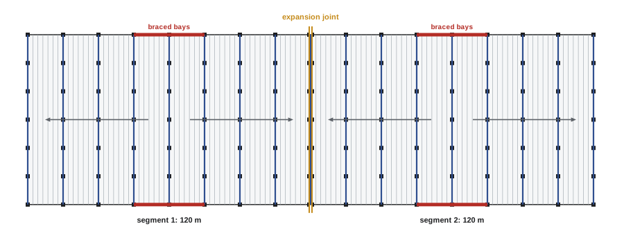
A 240 m building could move about 100 mm at each end for a 70 K range, and a steel member prevented from moving would develop forces over 1,000 kN, enough to damage connections and bracing. Building codes do not set expansion joint spacing, but common practice is to provide expansion joints in steel buildings every 100 to 150 m, closer where the structure is heated unevenly or restrained by stiff bracing at both ends. Bracing is best located near the middle of each segment so that the ends can move freely. Expansion joints must be continued through the roof membrane, walls, fire separations and every service crossing them: busways, cable trays and pipes need flexible sections or expansion fittings at the joint, and a joint that is forgotten in a busway can tear it apart.
Connections and hanging loads
Steel members are joined by bolted and welded connections, usually designed by a connection engineer working for the fabricator, from forces given by the building engineer. Shear connections (simple clip angles or fin plates) transfer vertical load; moment connections and brace connections transfer larger forces and need careful detailing. For data centres, the most numerous connections are the hangers that support services from the structure: threaded rods, beam clamps and strut channels supporting cable trays, busways, sprinkler pipes, ductwork and liquid cooling distribution. Good practice:
- Coordinate hanging loads and locations with the structural engineer early; heavy busways and filled water pipes can weigh 50 to 200 kg per metre.
- Attach to joist panel points or to supplementary steel spanning between joists, not to the middle of joist chords or to deck.
- Use a unistrut or steel grid hung from the structure (a "service grid" or "trapeze") so services can be added without new attachments to the structure.
- Brace hanging services against earthquake sway in seismic regions, as required by codes and standards (Lesson 7).
- Avoid welding to existing joists in operating buildings: hot work creates fire risk and can weaken thin joist members.
Fire protection and corrosion
Steel loses strength at high temperatures, retaining only about half its yield strength at about 550 to 600 °C. Building codes set required fire-resistance ratings for structural members depending on building size, occupancy and sprinkler protection. Many single-storey sprinklered data centres of non-combustible construction need no fire resistance for the roof structure; multi-storey buildings and fire separations do. Where required, steel is protected with spray-applied fire-resistive material, intumescent coatings that swell when heated, or board encasement. Spray-applied materials can shed fibres and dust, which are undesirable in data halls, so encapsulated or intumescent systems are often specified in white space.
Inside conditioned data halls, steel corrosion is negligible and a shop primer or no coating may suffice. Exposed steel outdoors, such as dunnage for rooftop equipment, generator yard structures and canopies, needs hot-dip galvanizing or a durable paint system, and attention to details that trap water. Cooling towers and their supports are exposed to wet, chemically treated air and need corrosion-resistant materials.
Coordinating structure and services
In a data hall, structure and services compete for the same space between the top of the racks and the roof. A typical section from the floor up includes racks of about 2.4 m, hot aisle containment to about 3 m, one or more levels of cable tray, busways, fire detection and sprinklers, lighting, and, increasingly, liquid cooling pipework, all below joists 0.9 to 1.5 m deep. Collaborative BIM models, early agreement of service zones (for example, a zone below the joists reserved for each trade), and structural designs that keep the bottom chords of joists and girders at a consistent level make installation and future changes much easier. Deeper joists with large web openings allow ducts and pipes to pass through the structure rather than below it, gaining clear height.
Common mistakes
MistakeUsing warehouse collateral loads for a data centre roof.
InsteadSpecify realistic collateral and hanging loads, often 0.5 to 1.5 kPa extra.
MistakeHanging heavy services from the middle of joist chords.
InsteadLoad panel points or provide supplementary framing.
MistakeOmitting expansion joints in very long buildings.
InsteadProvide joints every 100 to 150 m and continue them through services.
MistakeLocating braced frames without coordinating openings and service routes.
InsteadFix bracing locations early with architects and MEP designers.
MistakeAssuming steel grade controls deflection.
InsteadStiffness depends on section shape; all steels have E = 200 GPa.
Summary and key terms
- Structural steel of about 350 MPa yield is designed to CSA S16 in Canada or AISC 360 in the US.
- Beams are checked for bending, lateral-torsional buckling, shear, deflection, vibration and ponding.
- Heavy collateral and hanging loads often govern data centre roof members.
- Open-web joists and joist girders are economical for long spans but must be given every load and its location.
- Steel deck diaphragms and braced frames, moment frames or shear walls carry lateral loads to the foundations.
- Long buildings need expansion joints every 100 to 150 m, continued through services.
- Hangers, fire protection, corrosion protection and service coordination complete the design.
- Plastic section modulus
- The section property giving full plastic moment capacity, \(M_p = Z F_y\).
- Lateral-torsional buckling
- Sideways buckling and twisting of an unbraced beam.
- Collateral load
- Dead load from services and equipment added to the structure.
- Open-web steel joist
- A lightweight steel truss used to support roofs and floors.
- Joist girder
- A deep truss supporting joists at panel points.
- Panel point
- A truss joint where web members meet a chord.
- Diaphragm
- A horizontal element that distributes lateral loads to vertical systems.
- Braced frame
- A frame using diagonal members to resist lateral loads.
- Expansion joint
- A separation allowing thermal movement between building segments.
- Intumescent coating
- A fire-protective coating that swells when heated.
Practice problems
Work each problem on paper first, then reveal the answer to check.
Factored moment for 40 kN/m over 12 m simply supported?
Show answer
\(40 \times 144/8 = 720\) kN·m.
Moment resistance of a braced section with Z = 3,000 × 10³ mm³ and F_y = 350 MPa?
Show answer
\(0.9 \times 0.003 \times 350{,}000 = 945\) kN·m.
Deflection limit at span/360 for a 12 m beam?
Show answer
33 mm.
Does high-strength steel reduce deflection?
Show answer
No; E is the same, so deflection depends on the section.
Where should heavy hangers attach to a joist?
Show answer
At panel points or supplementary framing.
What does a roof deck diaphragm do?
Show answer
Collects lateral loads and delivers them to bracing or walls.
Thermal movement of a 150 m steel building for 50 K?
Show answer
\(12 \times 10^{-6} \times 150 \times 50 = 0.09\) m.
Typical expansion joint spacing for steel buildings?
Show answer
About 100 to 150 m.
At about what temperature does steel retain half its strength?
Show answer
About 550 to 600 °C.
Why are intumescent coatings often preferred in data halls?
Show answer
Spray-applied fireproofing can shed dust and fibres.
Lesson quiz · 5 questions
Score 60% or more to complete this lesson.
Create a free account to save your progress, take quizzes and earn a certificate.