
DCE-340 · Lesson 9 of 12 · 32 min
Redundancy architectures: N+1, 2N, distributed and block
Every component in a backup power system can fail, and every component must eventually be maintained. Redundancy is how a data centre keeps the IT load running through both. But redundancy is expensive: a fully duplicated power system doubles the capital cost of the most expensive part of the building and leaves half of it idle. The art of power architecture is to choose how much redundancy to provide, where to provide it, and how to arrange it so that the money buys real protection rather than complexity. This lesson defines the terms, compares the main architectures, introduces availability calculations, and looks at how the choices are changing for AI facilities.
Counting redundancy
Redundancy is described relative to N, the number of units needed to carry the design load:
- N: exactly enough capacity, with no spare. Any failure or maintenance outage affects the load.
- N+1: one spare unit. If one of five UPS modules is needed for redundancy, four carry the load (N = 4) and five are installed. N+2 adds a second spare, useful when units are large in number or one may be out for maintenance when another fails.
- 2N: two complete, independent systems, each able to carry the whole load. Also called system plus system.
- 2(N+1) or 2N+1: two systems, each with its own spare, or two systems plus a shared spare.
N+1 at the module level does not make a system N+1 overall: if five UPS modules share one output bus and one output breaker, the bus and breaker are single points of failure. Redundancy has to be examined along the whole path from utility to rack, including switchgear, cables, transfer equipment, controls and the cooling that keeps everything working.
Concurrent maintainability and fault tolerance
Two properties define what redundancy achieves:
- Concurrent maintainability: every component and distribution path can be taken out of service for planned maintenance, repair or replacement without shutting down the IT load. During that maintenance, the load may be exposed to a single failure.
- Fault tolerance: the facility can survive any single unplanned failure, such as a breaker trip, cable fault, fire in one room or human error on one system, without affecting the IT load. This requires independent paths that are physically separated (compartmentalized), so that one event cannot affect both.
The Uptime Institute's Tier Standard: Topology is the most widely used classification. TIA-942 (Rated-1 to Rated-4) and EN 50600 (availability classes 1 to 4) are broadly similar in intent.
| Tier | Description | Typical power architecture | Key requirement |
|---|---|---|---|
| I | Basic capacity | N: single path, no redundant components | Dedicated space, UPS and generator |
| II | Redundant capacity components | N+1 components on a single path | Spare UPS modules, generators, chillers |
| III | Concurrently maintainable | N+1 components, two distribution paths (one may be passive) | Any component or path can be maintained without shutdown |
| IV | Fault tolerant | 2N or distributed redundant, two active, compartmentalized paths | Any single failure is survived; continuous cooling |
A Tier III facility with dual-corded IT equipment typically has two distribution paths from the switchgear to the racks, but they may share redundant UPS and generator capacity. A Tier IV facility needs two active, isolated paths, each able to carry the load, and compartmentalization so that a fire or flood in one path's rooms does not reach the other.
Dual-corded IT equipment
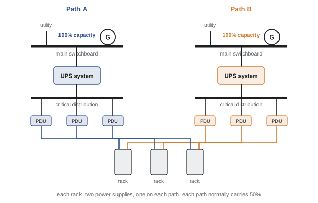
Most enterprise servers, storage and network equipment have two power supplies (or more), each able to run the equipment alone. Each power supply is connected to a different power path, A and B, and in normal operation they share the load roughly equally. If one path fails, the other power supply takes the full load instantly with no interruption. Dual-corded loads are what allow 2N and distributed redundant architectures to deliver fault tolerance at the rack.
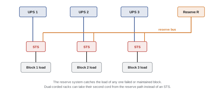
Equipment with a single cord, or with N+1 power supplies that are not split evenly across paths, needs a transfer device: a rack-mounted automatic transfer switch, or a static transfer switch (STS) upstream that switches between two UPS sources in a quarter of a cycle. STSs restore fault tolerance for single-corded loads but are themselves a single point of failure for the loads they serve.
A frequent field problem is circuit loading. In a 2N design, each rack power strip carries half the load normally but must be able to carry all of it when the other path fails. If each circuit is loaded to more than half its usable capacity in normal operation, a path failure will overload the surviving circuits and trip them, turning a redundant system into a total outage.
Worked problem
Loading dual-corded rack circuits
A rack has two 208 V, 30 A single-phase circuits, one from path A and one from path B. Circuit breakers must not carry more than 80% of their rating continuously. What is the maximum normal current per circuit, and the maximum rack load?
Show solution
- Continuous limit per circuit: \(0.8 \times 30 = 24\) A.
- If either circuit fails, the other must carry the whole rack, so the total rack current must not exceed 24 A, which means each circuit carries at most 12 A normally (40% of its rating).
- Maximum rack load: \(24 \times 208 = 4990\) VA, about 5 kVA.
Answer: At most 12 A per circuit in normal operation and about 5 kVA per rack. Monitoring systems should alarm when the sum of the A and B currents approaches 24 A, not when one circuit reaches 24 A.
The main architectures
N+1 parallel redundant
Several UPS modules (N+1) are paralleled on a common output bus feeding the critical distribution. It is the simplest and cheapest redundant design, and it handles the failure of any one module. However, the output switchboard, bus and downstream distribution form a single path: a fault on the bus or a breaker failure drops the whole load, and maintaining the bus requires a shutdown or a transfer to maintenance bypass (raw utility). This is typical of Tier II designs and of many enterprise and colocation halls with a second, non-UPS path added for concurrent maintainability.
2N (system plus system)
Two completely independent systems, A and B, each with its own utility feed or transformer, generators, switchgear, UPS and distribution, each sized for the whole load, feed the two cords of every rack. Any component or entire path can fail or be maintained while the other carries the load. 2N is the simplest fault-tolerant design to understand and operate, and it is common in enterprise and financial data centres. Its drawback is cost: each system can be loaded to at most 50% of its capacity, so half the installed UPS and generator capacity is always idle, and in practice utilization is lower still because systems are not loaded to 100%.
Distributed redundant
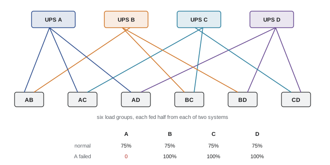
Distributed redundant architectures (also called "N+1 distributed" or by ratios such as "4-to-make-3") use N+1 independent UPS systems, but instead of pairing them A and B, each system feeds several load groups, and each load group is fed from a different pair of systems. With four systems there are six possible pairs (AB, AC, AD, BC, BD, CD), so the critical load is divided into six groups, each fed half from each of its two systems. If one system fails, its share of each group shifts to the partner systems, spreading the extra load over all the survivors.
Each system can be loaded to N/(N+1) of its capacity in normal operation: 75% for 4-to-make-3, 80% for 5-to-make-4. Utilization is therefore much higher than 2N's 50%, while dual-corded racks still see two independent sources, so the design is fault tolerant. The cost is complexity: the load group pairings, normal and failure loads of every system, and the effect of maintenance have to be tracked carefully, and capacity must be added in a balanced way. Distributed redundant designs are common in large colocation and hyperscale facilities.
Worked problem
Distributed redundant loading
A 4-to-make-3 distributed redundant design uses four 1.5 MW UPS systems. The IT load of 4.5 MW is divided equally among the six load groups AB, AC, AD, BC, BD and CD, each fed half from each of its systems. Find each system's normal load, and the loads after system A fails.
Show solution
- Each load group: \(4.5/6 = 0.75\) MW, split 0.375 MW per system.
- Each system feeds three groups: \(3 \times 0.375 = 1.125\) MW, which is \(1.125/1.5 = 75\%\).
- If A fails, groups AB, AC and AD move entirely to B, C and D respectively. B now carries \(1.125 + 0.375 = 1.5\) MW, as do C and D: each at 100%.
Answer: Each system runs at 75% normally and 100% after a failure, so the 4.5 MW load uses 6 MW of installed UPS (75% utilization) instead of the 9 MW a 2N design would need. The load groups must be kept balanced as the IT load grows, or a failure will overload one system.
Block redundant (catcher)
In a block redundant or "catcher" design, the critical load is divided into N blocks, each fed by its own active UPS system, and one reserve UPS system is shared by all of them. Each block's distribution has a transfer arrangement, usually a static transfer switch or the UPS's own bypass, that can take power from the reserve system if the block's primary system fails or is being maintained. The reserve system "catches" whichever block needs it.
Block redundancy gives N/(N+1) utilization like distributed redundancy, but with a simpler and more uniform layout that suits building in repeated blocks of 1.5 to 3 MW. The reserve system is normally unloaded (or lightly loaded), which makes its readiness important to verify. A common variant, isolated redundant, feeds each active UPS's static bypass from the reserve system, so that a failure of the active UPS transfers the load to the reserve through the bypass without separate STSs. Some designs use the reserve to back up the mechanical loads as well.
| Architecture | Fault tolerant at rack? | Concurrently maintainable? | Maximum normal UPS loading | Complexity |
|---|---|---|---|---|
| N+1 parallel (single bus) | No | Only with a second path | (N)/(N+1) of the bus capacity | Low |
| 2N | Yes | Yes | 50% | Low to medium |
| Distributed redundant (N+1 systems) | Yes, with dual-corded loads | Yes | N/(N+1): 75% for 4-to-make-3 | High |
| Block redundant (catcher) | Yes, with STS or dual-corded loads | Yes | N/(N+1) for active blocks | Medium |
| 2(N+1) | Yes | Yes, even during maintenance | Below 50% | Medium, highest cost |
Availability calculations
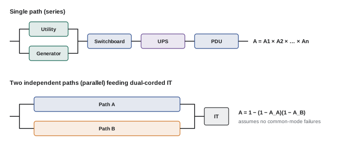
Availability is the fraction of time a system is working. For a component that fails on average every MTBF hours (mean time between failures) and takes MTTR hours to repair, the steady-state availability is \(A = \mathrm{MTBF}/(\mathrm{MTBF} + \mathrm{MTTR})\). Availability is often expressed in "nines": 99.99% (four nines) allows 53 minutes of downtime a year, and 99.999% allows about 5 minutes.
For a series system, in which every component must work (a single path), availabilities multiply: \(A = A_1 A_2 \cdots A_n\). For a parallel system, in which any one of the redundant components suffices, unavailabilities multiply: \(A = 1 - (1 - A_1)(1 - A_2)\). Reliability block diagrams combine these rules for whole systems.
Worked problem
Single path versus 2N
One power path consists of a source (utility with generator backup) of availability 0.99999, a switchboard of 0.99998, a UPS system of 0.99995 and a PDU of 0.99999, all in series. Find the availability and annual downtime of one path, and of two independent paths in parallel feeding dual-corded loads.
Show solution
- One path: \(A = 0.99999 \times 0.99998 \times 0.99995 \times 0.99999 = 0.99991\). Unavailability \(9.0 \times 10^{-5}\), or \(9.0 \times 10^{-5} \times 525{,}600 = 47\) minutes a year.
- Two independent paths: unavailability \((9.0 \times 10^{-5})^2 = 8.1 \times 10^{-9}\), or 0.004 minutes (about a quarter of a second) a year.
Answer: About 47 minutes a year for one path versus a fraction of a second for two independent paths. In reality the 2N result is far too optimistic: common-mode failures (a shared control system, a fire, a design error) and human error dominate, so real 2N facilities achieve perhaps 99.999% rather than the theoretical figure. Independence, not just duplication, is what delivers the benefit.
Industry outage surveys consistently find that power problems are the largest single cause of significant data centre outages, and that a large share of incidents involve human error: incorrect switching, inadequate procedures, or procedures not followed. Commissioning, integrated systems testing, method statements for every switching operation, training and change control are therefore as important as the architecture itself. A simple, well-understood design that operators can switch correctly at 3 a.m. often outperforms a complex one on paper.
Redundancy for AI facilities
AI training clusters change the trade-offs. A training job runs across thousands of accelerators for weeks and checkpoints its progress periodically; losing power to part of the cluster stops the job, but it restarts from the last checkpoint rather than losing customer transactions. At the same time, AI halls draw 100 kW or more per rack, so each megawatt of redundant UPS and generator capacity is a large cost. Some operators therefore build training halls with less redundancy, for example N or N+1 UPS with fewer generators, or even no generator backup for part of the load, while keeping inference, storage and network equipment on fully redundant 2N or distributed redundant power. Others use block redundant designs with large blocks matched to cluster sizes.
AI loads also behave differently: synchronized training steps can make a whole cluster's power swing by tens of percent within a fraction of a second, which stresses UPSs, generators and the grid connection. Battery energy storage and UPS control features that smooth these swings are becoming part of the backup power design.
Lesson 10 shows how redundancy is proven by testing failures under load, Lesson 11 how operations keep it intact day to day, and Lesson 12 applies these architectures in a full design.
Common mistakes
MistakeCalling a system N+1 when the output bus or breaker is a single point of failure.
InsteadTrace redundancy along the entire path from source to rack.
MistakeLoading each cord of a dual-corded rack above 40% of its breaker rating.
InsteadKeep the combined A+B current within the continuous limit of one circuit.
MistakeLetting distributed redundant load groups drift out of balance as IT is added.
InsteadTrack each system's normal and failure loads and place new equipment to keep them balanced.
MistakeTreating calculated 2N availability as real.
InsteadCommon-mode failures and human error dominate; ensure physical and control independence and strong procedures.
MistakeAssuming the reserve system in a catcher design is ready because it carries no load.
InsteadTest the reserve system and transfer path regularly under load.
Summary and key terms
- N is the capacity needed; N+1 adds a spare unit; 2N duplicates the whole system.
- Concurrent maintainability allows planned work without shutdown; fault tolerance survives any single failure.
- Uptime Tiers: I (N), II (N+1 components), III (concurrently maintainable), IV (fault tolerant, compartmentalized).
- Dual-corded IT equipment enables fault tolerance at the rack; single-corded loads need transfer switches.
- In 2N, each cord's circuit must be loaded to no more than half its continuous limit.
- N+1 parallel designs are cheap but have a single distribution path.
- 2N is simple and fault tolerant but limits UPS loading to 50%.
- Distributed redundant (4-to-make-3) and block redundant (catcher) designs achieve N/(N+1) loading with more complexity.
- Series availabilities multiply; parallel unavailabilities multiply; common-mode failures and human error limit real availability.
- AI training halls may use reduced redundancy, while inference and storage remain fully redundant.
- N
- The number of units needed to carry the design load.
- N+1
- N units plus one redundant unit.
- 2N
- Two complete independent systems, each able to carry the whole load.
- Concurrent maintainability
- The ability to maintain any component or path without shutting down the load.
- Fault tolerance
- The ability to survive any single unplanned failure without affecting the load.
- Compartmentalization
- Physical separation of redundant paths so that one event cannot affect both.
- Dual-corded
- IT equipment with two power supplies connected to separate paths.
- Static transfer switch (STS)
- A solid-state switch that transfers a load between two sources within a fraction of a cycle.
- Distributed redundant
- An architecture in which N+1 systems feed load groups on different pairs of systems.
- Block redundant
- An architecture in which N active blocks share a reserve system (catcher).
- Availability
- The fraction of time a system is operational: MTBF/(MTBF + MTTR).
- MTBF
- Mean time between failures.
- MTTR
- Mean time to repair.
- Common-mode failure
- A single cause that disables redundant components simultaneously.
Practice problems
Work each problem on paper first, then reveal the answer to check.
A load of 1.8 MW is served by 500 kW UPS modules. How many modules are needed for N, N+1 and 2N?
Show answer
N = 4, N+1 = 5, 2N = 8.
What is the difference between concurrent maintainability and fault tolerance?
Show answer
Concurrent maintainability covers planned maintenance without shutdown; fault tolerance covers surviving unplanned failures.
A rack is fed by two 208 V 3-phase 30 A circuits (A and B). With an 80% continuous limit, what is the maximum rack load?
Show answer
One circuit must carry all: 0.8 × 30 × 208 × 1.732 = 8.6 kVA.
What is the maximum normal loading of each system in a 5-to-make-4 distributed redundant design?
Show answer
4/5 = 80%.
How many load groups does a full 5-system distributed redundant pairing have?
Show answer
C(5,2) = 10.
A 2N design uses two 3 MW UPS systems. What is the maximum IT load, and the utilization of installed UPS capacity?
Show answer
3 MW; 3/6 = 50% maximum.
A component has MTBF 200,000 h and MTTR 8 h. What is its availability?
Show answer
200,000/200,008 = 0.99996.
Two components of availability 0.9995 are in parallel. What is the combined availability?
Show answer
1 − (0.0005)² = 0.99999975.
Why are calculated 2N availabilities unrealistically high?
Show answer
They assume independent failures; common-mode failures and human error affect both paths.
Why might an AI training hall be built with less redundancy than an inference hall?
Show answer
Training can restart from checkpoints, so the cost of an outage is lower, while redundant capacity for 100 kW racks is very expensive.
Lesson quiz · 5 questions
Score 60% or more to complete this lesson.
Create a free account to save your progress, take quizzes and earn a certificate.