
DCE-340 · Lesson 8 of 12 · 29 min
Protection and coordination with backup sources
Protective devices, breakers, fuses and relays, must clear faults quickly and selectively: only the device nearest the fault should open, leaving the rest of the system in service. In a facility fed by a utility transformer, this is a familiar design task (DCE-310). Backup power complicates it, because each source behaves differently during a fault. A utility transformer delivers tens of thousands of amperes; a generator delivers a high current that decays within a second; a UPS inverter delivers little more than its rating and then shuts down or transfers; a battery can deliver enormous DC current. Protection designed only for the utility case may fail to clear faults, or clear the wrong breaker, when the facility runs on backup. This lesson covers fault current from each source, coordination across operating modes, ground-fault protection with multiple sources, arc flash considerations, and the studies that bring them together.
Fault current from different sources
A three-phase fault at the terminals of a source draws a current limited by the source's internal impedance:
- Utility transformer: limited by the transformer impedance (typically 5% to 6% for distribution transformers), plus the utility system impedance. A 2,500 kVA, 480 V transformer with 5.75% impedance delivers about 17 times its rated current, sustained until a device clears it.
- Synchronous generator: limited by the machine's reactances, which rise over time after the fault. The subtransient reactance \(X''_d\) (typically 0.10 to 0.20 per unit) sets the first few cycles; the transient reactance \(X'_d\) the next fraction of a second; the synchronous reactance \(X_d\) (often above 1.5 per unit) the steady state, where current can fall below rated unless the excitation system supports it.
- UPS inverter: limited electronically to protect its semiconductors, typically 1.5 to 3 times rated current for tens to hundreds of milliseconds; then the UPS either transfers to static bypass (if a healthy bypass source exists) or shuts down.
- Batteries: can deliver very high DC currents, limited only by internal resistance and connections; DC protection must interrupt them (Lesson 4).
import numpy as np

# Fault current from a 2,500 kVA, 480 V generator after a three-phase fault at its terminals
S, V = 2500e3, 480.0
I_rated = S / (np.sqrt(3) * V)
xdpp, xdp, xd = 0.14, 0.22, 2.2            # per-unit subtransient, transient, synchronous reactances
tdpp, tdp = 0.03, 0.4                       # time constants, s
def i_fault(t):
    return I_rated * ((1 / xdpp - 1 / xdp) * np.exp(-t / tdpp) + (1 / xdp - 1 / xd) * np.exp(-t / tdp) + 1 / xd)

print(f"rated current {I_rated:,.0f} A")
for t in (0.0, 0.05, 0.1, 0.5, 1.0, 3.0):
    print(f"  t = {t:4.2f} s: fault current {i_fault(t):8,.0f} A ({i_fault(t) / I_rated:4.1f} x rated)")
print("with a permanent-magnet exciter or excitation support, current is held near 3 x rated for about 10 s")

# Utility supply at the same switchboard for comparison: 2,500 kVA transformer, 5.75% impedance
I_util = I_rated / 0.0575
print(f"utility transformer fault current about {I_util:,.0f} A ({I_util / I_rated:.1f} x rated), sustained")

# UPS inverter: current-limited to 1.5 x rated for 100 ms, then it transfers to bypass or shuts down
ups_kva = 750e3
print(f"750 kVA UPS inverter fault current about {1.5 * ups_kva / (np.sqrt(3) * V):,.0f} A for about 0.1 s")rated current 3,007 A t = 0.00 s: fault current 21,479 A ( 7.1 x rated) t = 0.05 s: fault current 13,698 A ( 4.6 x rated) t = 0.10 s: fault current 11,226 A ( 3.7 x rated) t = 0.50 s: fault current 4,891 A ( 1.6 x rated) t = 1.00 s: fault current 2,377 A ( 0.8 x rated) t = 3.00 s: fault current 1,374 A ( 0.5 x rated) with a permanent-magnet exciter or excitation support, current is held near 3 x rated for about 10 s utility transformer fault current about 52,296 A (17.4 x rated), sustained 750 kVA UPS inverter fault current about 1,353 A for about 0.1 s
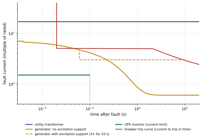
The comparison shows the core problem. On utility power, a downstream breaker sees over 50,000 A and trips instantly. On generator power, the same fault produces about 21,000 A at first, falling below rated current within a second; on UPS inverter power, it produces only about 1,350 A for a tenth of a second. A breaker set to trip instantaneously at 10,000 A clears the utility fault, may clear the generator fault in its first cycles, and never sees the UPS fault.
Generators and fault clearing
Because generator fault current decays, downstream breakers with long-time or short-time delays may never trip if the current falls below their pickup before their delay ends. Remedies include:
- Excitation support: permanent-magnet generator (PMG) exciters or excitation boost systems that hold fault current near three times rated for about 10 seconds, long enough for downstream devices to operate.
- Protective settings chosen for both sources: instantaneous or short-time pickups low enough to see generator fault current, while still coordinating with upstream devices.
- Generator protection relays that detect faults by voltage-restrained overcurrent, which lowers the pickup as voltage collapses during a fault.
Worked problem
Will the breaker trip on generator power?
A 1,200 A feeder breaker has a short-time pickup of 6 times its rating (7,200 A) with a 0.3 s delay. On generator power, a fault on the feeder draws the current computed above. Will the breaker trip?
Show solution
- The breaker needs current above 7,200 A to persist for 0.3 s.
- From the decrement: 11,226 A at 0.1 s but 4,891 A at 0.5 s; current falls below 7,200 A at about 0.3 s, just as the delay ends.
- With excitation support holding about 9,000 A (3 × rated), the current stays above pickup.
Answer: Without excitation support, marginal at best: the current may fall below pickup before the delay ends, leaving the fault to the generator's own protection, which would drop the whole bus. With excitation support, the breaker trips selectively. This is why PMG exciters are specified for data centre generators.
UPS output faults
With the UPS on inverter, its limited fault current may not trip downstream breakers. Designs handle this in several ways:
- Static bypass transfer: during a downstream fault, the UPS transfers to its bypass source (utility or generator), which supplies enough current to clear the fault, and then returns to inverter. This works only if the bypass source is healthy, so it fails during an outage when the UPS is on battery.
- Small branch circuits with fast devices: breakers or fuses in PDUs and rack distribution (for example 20 A to 63 A) operate on currents the UPS can supply.
- Selective coordination of the UPS output distribution checked for inverter-only operation, so that a fault in one rack PDU does not trip a larger upstream device or shut down the UPS.
Worked problem
Clearing a rack fault on battery
A 500 kVA UPS (rated 601 A at 480 V) limits fault current to 2 times rated for 200 ms. A fault occurs in a rack fed by a 32 A breaker downstream of a 225 A PDU breaker, during a utility outage before generators start. Which devices can clear it?
Show solution
- Available current: about \(2 \times 601 = 1{,}202\) A for 200 ms (less after transformer and cable impedance).
- The 32 A breaker's instantaneous trip (typically 10 to 20 times rating, 320 to 640 A) operates within a few milliseconds.
- The 225 A breaker's instantaneous pickup (often 10 times, 2,250 A) is not reached.
Answer: The 32 A rack breaker clears the fault selectively; the PDU breaker and the UPS ride through. Larger faults upstream, at the 225 A level, might not be cleared until the UPS shuts down, which is why critical distribution keeps protective devices small and close to loads.
Coordination across operating modes
A data centre power system operates in several modes: normal utility supply, utility with a tie breaker closed, generators alone, generators in parallel with some units out, UPS on battery, UPS on bypass, maintenance configurations. Selective coordination must be checked for each mode that matters, since fault currents and source behaviour differ. Protection settings are a compromise: settings that coordinate perfectly at utility fault levels may not trip on generator power; settings low enough for the generator may trip unnecessarily on utility power. Modern electronic trip units and relays offer multiple setting groups, switched automatically according to the source (for example, an alternate setting group activated when the generator breaker closes).
In Canada, the CEC requires selective coordination for emergency systems and some other critical systems, and CSA standards and owner requirements set expectations for data centres; protection studies are typically sealed by a professional engineer.
Grounding and ground-fault protection with multiple sources
Large low-voltage services above a set size require ground-fault protection of equipment, which detects current returning by paths other than the neutral. With generators and transfer switches, ground-fault sensing can be confused: if the neutral is solidly connected through a transfer switch (a three-pole switch), ground-fault current can return by two paths, and the ground-fault relay at the service or generator may see only part of it, or see neutral current as ground fault. Solutions include:
- Four-pole transfer switches that switch the neutral, making each generator a separately derived system with its own neutral-ground bond (Lesson 7).
- Careful placement of ground-fault sensors and the use of modified differential ground-fault schemes in multi-source systems.
- Resistance grounding of generators and some low-voltage systems, which limits ground-fault current and allows continued operation during a first ground fault, with alarms (common for medium-voltage generators).
These choices are made together with the transfer switch design, and verified in testing (Lesson 10).
Arc flash across modes
Arc flash incident energy depends on fault current and on how long the protective device takes to clear it. Counterintuitively, lower fault currents can produce higher incident energy: on generator power, the lower current may move a breaker from its instantaneous region into a delayed region, so the arc lasts longer. Arc flash studies therefore calculate incident energy in each operating mode and label equipment for the worst case. Techniques to reduce incident energy include:
- Maintenance (energy-reducing) switches that temporarily set breakers to instantaneous trip during work.
- Zone-selective interlocking, which lets the breaker nearest a fault trip without delay while upstream breakers wait.
- Arc flash relays that detect light and current and trip within milliseconds.
- Remote racking and switching, so workers are away from equipment when operating it.
Worked problem
Lower current, longer arc
On utility power, an arcing fault at a switchboard draws 30 kA and the main breaker clears in 0.05 s. On generator power, it draws 12 kA and the breaker clears in its short-time band at 0.5 s. Incident energy is roughly proportional to current times time. Compare the two cases.
Show solution
- Utility: \(30 \times 0.05 = 1.5\) kA·s.
- Generator: \(12 \times 0.5 = 6.0\) kA·s.
Answer: About four times the incident energy on generator power, despite less than half the current. The arc flash label must reflect the generator case, or settings must change (for example, a maintenance mode) when the generator supplies the bus.
Protection studies
Protection of a data centre is designed and documented through a set of engineering studies, typically performed with specialized software:
- Short-circuit study: fault currents at every bus in every relevant operating mode, to verify equipment interrupting and withstand ratings.
- Coordination study: time-current curves of protective devices, settings to achieve selectivity, and documentation of any compromises.
- Arc flash study: incident energy and arc flash boundaries at each piece of equipment, producing labels.
- Load flow and motor starting studies, especially for generator capacity and voltage dips (Lesson 5).
Studies are updated whenever the system changes: new generators, UPS replacements, utility changes in available fault current, or setting changes. Settings in the field are verified against the study during commissioning (Lesson 10).
Common mistakes
MistakeCoordinating protection for utility fault levels only.
InsteadCheck every operating mode, including generator-only and UPS-on-battery.
MistakeAssuming generators sustain high fault current.
InsteadAccount for decrement; specify excitation support so downstream devices trip.
MistakeRelying on UPS inverter fault current to clear large faults.
InsteadKeep downstream devices small and fast; rely on bypass only when it is available.
MistakeIgnoring ground-fault sensing errors with three-pole transfer switches.
InsteadDesign the neutral switching and ground-fault scheme together.
MistakeLabelling arc flash for the highest fault current only.
InsteadCalculate incident energy in every mode; lower current can mean a longer, worse arc.
Summary and key terms
- Utility, generator, UPS and battery sources deliver very different fault currents.
- Generator fault current decays; excitation support keeps it high enough for downstream tripping.
- UPS inverters limit fault current; small, fast downstream devices and bypass transfer clear faults.
- Selective coordination must hold in every operating mode, using setting groups where needed.
- Multiple sources complicate ground-fault sensing; neutral switching and grounding are designed together.
- Arc flash energy can rise on backup sources; short-circuit, coordination and arc flash studies document it all.
- Fault current
- The current that flows into a short circuit.
- Subtransient reactance
- The generator reactance governing the first cycles of a fault.
- Decrement
- The decay of generator fault current over time.
- PMG exciter
- A permanent-magnet generator exciter that sustains fault current.
- Current limit
- Electronic limiting of an inverter's output current.
- Selective coordination
- Only the device nearest a fault opens.
- Setting group
- An alternate set of protective settings selected by operating mode.
- Zone-selective interlocking
- Communication between breakers so the nearest trips without delay.
- Incident energy
- The thermal energy at a working distance from an arc.
- Coordination study
- An analysis of protective device curves and settings.
Practice problems
Work each problem on paper first, then reveal the answer to check.
Fault current of a 1,500 kVA, 480 V transformer at 5.75% impedance (infinite source)?
Show answer
1,804/0.0575 ≈ 31,400 A.
Initial fault current of a generator with X″d = 0.12 per unit?
Show answer
About 8.3 times rated.
Why may a delayed breaker not trip on generator power?
Show answer
Fault current decays below pickup before the delay ends.
What does a PMG exciter do during a fault?
Show answer
Holds fault current near 3 times rated for about 10 s.
Fault current of a 300 kVA, 480 V UPS limited to 2 × rated?
Show answer
About 722 A.
When does UPS bypass transfer fail to help clear a fault?
Show answer
When the bypass source is lost, as during an outage.
What are setting groups used for?
Show answer
Different protective settings for different sources or modes.
Why do four-pole transfer switches help ground-fault protection?
Show answer
They separate neutral paths so sensors see the true fault current.
Relative incident energy: 20 kA for 0.1 s versus 8 kA for 0.6 s?
Show answer
2 versus 4.8 kA·s: the second is worse.
Name three protection studies.
Show answer
Short-circuit, coordination and arc flash.
Lesson quiz · 5 questions
Score 60% or more to complete this lesson.
Create a free account to save your progress, take quizzes and earn a certificate.