
DCE-340 · Lesson 1 of 12 · 34 min
UPS topologies
A data centre promises its customers that the servers will not lose power, ever. The utility cannot keep that promise: even a very reliable grid delivers several momentary interruptions and dozens of voltage sags a year, and occasionally an outage lasting hours. Servers, on the other hand, tolerate an interruption of only about 10 to 20 milliseconds before their power supplies drop out. Backup power closes that gap with two layers: an uninterruptible power supply (UPS), which carries the load instantly from stored energy for seconds to minutes, and standby generators, which start, take over the load and run for as long as fuel lasts. Transfer switches and paralleling switchgear connect the pieces, and the redundancy architecture decides how many of each are needed so that a failure or a maintenance outage never reaches the IT load.
This course follows that chain, from the utility supply through UPS, batteries, generators and transfer equipment to protection, redundancy, testing and operations. This lesson covers the UPS itself: the power problems it must ride through, the main topologies, ratings, efficiency and bypass arrangements. The section at the end of this lesson sets out how the twelve lessons fit together. The course builds on the distribution systems of DCE-310.
What the UPS protects against
Disturbances on the utility supply range from microseconds to hours:
- Transients and surges: microsecond spikes from lightning and switching, handled mainly by surge protective devices.
- Sags (dips): drops to 10 to 90% of nominal voltage for half a cycle to a minute, usually caused by faults elsewhere on the network that are cleared by protection. Sags are the most common disturbance by far.
- Swells: brief rises, for example when a large load is disconnected or during a ground fault on another phase.
- Momentary interruptions: loss of voltage for a fraction of a second to a few seconds while utility reclosers clear a temporary fault.
- Sustained outages: anything longer, from minutes to days after storms.
- Frequency variations, harmonics and voltage unbalance, which matter more when running on generators or weak grids.
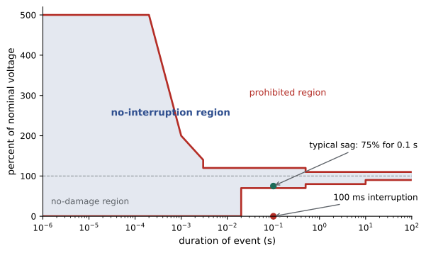
The tolerance of IT equipment is described by the ITIC curve (formerly the CBEMA curve), published by the Information Technology Industry Council for 120 V equipment and widely used as a reference for other voltages. It shows the voltage and duration combinations equipment should survive: for example 0% voltage (a complete interruption) for up to 20 ms, 70% for up to 0.5 s and 80% for up to 10 s. Disturbances outside the curve may cause the power supply to shut down, so the UPS must keep the output inside it whatever the input does.
UPS topologies
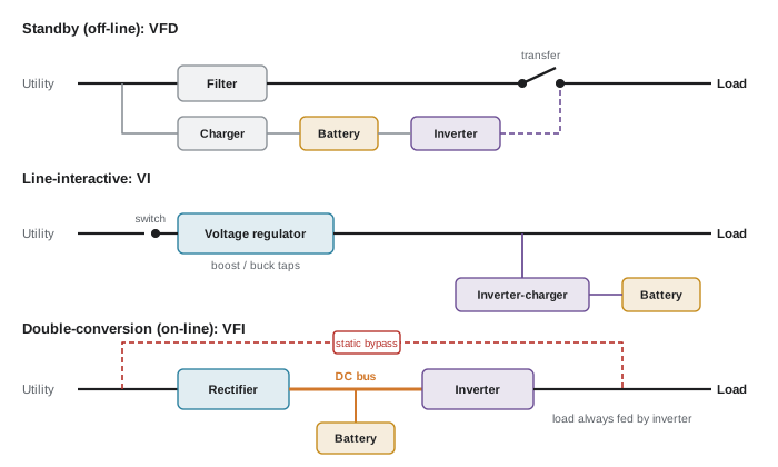
The international standard for UPS performance, IEC 62040-3, classifies UPSs by how their output depends on the input: VFD (voltage and frequency dependent), VI (voltage independent) and VFI (voltage and frequency independent). These correspond to the three static topologies used in practice.
Standby (off-line)
In normal operation, the load is fed directly from the utility through a filter. When the input fails or goes outside limits, a transfer switch connects an inverter powered from the battery. The transfer takes a few milliseconds (typically 2 to 10 ms) and the output waveform may be a stepped approximation of a sine wave. Standby UPSs are cheap and efficient (98 to 99%) but are classified VFD: the load sees every sag and frequency variation until the UPS decides to transfer. They are used for desktop computers and small network equipment, not data centres.
Line-interactive
A line-interactive UPS keeps the inverter connected in parallel with the load and adds a tapped autotransformer that boosts or bucks the voltage during sags and swells without using the battery. The inverter runs in reverse to charge the battery and takes over in an outage, with a very short transfer. Classified VI, line-interactive units suit edge sites, network closets and small server rooms up to a few kVA, and offer efficiency near 97 to 98%.
Double-conversion (on-line)
In a double-conversion UPS, the rectifier converts all incoming AC to DC, the DC bus charges the battery, and the inverter recreates clean AC for the load continuously. When the input fails, the rectifier simply stops and the battery feeds the DC bus with no transfer at all; the load cannot see the event. The output voltage and frequency are generated by the inverter, so the UPS is VFI: input sags, swells, frequency variations and generator instability never reach the load. Double conversion is the standard topology for data centres and large critical loads.
The penalty is losses: every watt passes through two conversion stages. Modern transformerless IGBT double-conversion UPSs reach about 96 to 97% efficiency at 50 to 100% load, falling at light load; older transformer-based units were nearer 92 to 94%.
| Topology | IEC 62040-3 class | Transfer to battery | Typical efficiency | Typical use |
|---|---|---|---|---|
| Standby (off-line) | VFD | 2 to 10 ms | 98 to 99% | Desktops, small devices |
| Line-interactive | VI | Under 4 ms | 97 to 98% | Network closets, edge, small rooms |
| Double-conversion | VFI | None (zero) | 94 to 97% (99% in eco-mode) | Data centres, critical loads |
| Rotary / DRUPS | VFI equivalent | None | 95 to 97% | Large sites wanting no batteries |
Eco-mode and energy-saver modes
Most large double-conversion UPSs offer an eco-mode in which the load is normally fed through the static bypass and the inverter idles, ready to take over within a few milliseconds when the input deviates. Efficiency rises to about 99%, but the load is exposed to input disturbances until transfer, effectively making the UPS VFD or VI. Newer "advanced eco-modes" keep the inverter running in parallel to filter harmonics and correct power factor, transferring in under 2 ms. Operators weigh the savings against the risk; many use eco-mode only when the input is stable and the UPS has redundant capacity.
Worked problem
Value of UPS efficiency
A data hall has 4 MW of IT load fed through double-conversion UPSs at 96.0% efficiency. Eco-mode would raise efficiency to 99.0%. The cooling system uses 0.25 W of electricity per watt of heat removed, and electricity costs $0.09/kWh. What is the annual saving from eco-mode, if used all year?
Show solution
- UPS input at 96.0%: \(4000/0.96 = 4166.7\) kW, losses 166.7 kW. At 99.0%: \(4000/0.99 = 4040.4\) kW, losses 40.4 kW.
- Reduction in losses: \(166.7 - 40.4 = 126\) kW. The losses are heat, so cooling power also falls by \(0.25 \times 126 = 32\) kW. Total saving 158 kW.
- Annual energy: \(158 \times 8760 = 1.38\) GWh; cost \(1{,}384{,}000 \times 0.09 = \$124{,}600\).
Answer: About $125,000 a year and 1.4 GWh, about 4% of the IT energy. This is why eco-modes are attractive, and why operators study the frequency of input disturbances at their site before adopting them.
Rotary UPS and flywheels
A rotary UPS uses a motor-generator set or a synchronous machine with a large rotating mass instead of (or as well as) an inverter. Flywheel energy storage spins a heavy rotor, often in a vacuum on magnetic bearings, and discharges it through a power converter during an interruption. Flywheels store enough energy for only 10 to 30 seconds at full load, but that is enough to start generators, and they avoid the chemistry and replacement cycle of batteries.
A diesel rotary UPS (DRUPS) combines a flywheel or induction coupling, a synchronous machine and a diesel engine on one shaft: in normal operation the machine filters the utility and stores kinetic energy, and on an outage the engine starts and clutches in within a few seconds while the stored energy carries the load. DRUPS units of 1 to 3 MW are popular in Europe and in some large North American sites because they eliminate batteries and separate generators, at the cost of mechanical complexity and higher noise.
Ratings: kVA, kW and power factor
A UPS has two output ratings: apparent power in kVA, limited by the inverter's current, and real power in kW, limited by its thermal and DC capacity. The ratio is the rated output power factor. Older UPSs were rated at 0.8 power factor (a 100 kVA unit delivered 80 kW); modern data centre UPSs are typically rated at unity (1.0), so kVA equals kW. IT loads with active power factor correction present a power factor of 0.95 to 0.99, often slightly leading at light load, which the UPS must be able to handle.
The load on a UPS must not exceed either rating. Designers normally load a UPS module to no more than about 80 to 90% of its rating in the worst case, which leaves margin for growth, load inrush and measurement error, and keeps the UPS in its efficient range.
Worked problem
Checking UPS capacity
A UPS is rated 500 kVA at 0.9 output power factor. The connected load draws 430 kVA at a power factor of 0.97. Is the UPS within its ratings? What is its percentage load?
Show solution
- UPS ratings: 500 kVA and \(0.9 \times 500 = 450\) kW.
- Load: 430 kVA and \(0.97 \times 430 = 417\) kW.
- kVA loading: \(430/500 = 86\%\). kW loading: \(417/450 = 93\%\).
Answer: Both are within rating, but the kW loading of 93% is the limiting value and above the usual 80 to 90% design target, so this UPS has almost no room for growth.
Inside a double-conversion UPS
Rectifier and input harmonics
Older UPSs used thyristor (SCR) rectifiers, which draw current in pulses and inject harmonics into the supply: a six-pulse rectifier has a current total harmonic distortion (THDi) around 30%, dominated by the 5th and 7th harmonics. Twelve-pulse rectifiers with phase-shifting transformers and passive filters reduced this to about 8 to 10%. Modern UPSs use IGBT active rectifiers that draw nearly sinusoidal current (THDi under 3 to 5%) at near-unity power factor. Low input distortion matters most when running on generators, whose high internal impedance turns harmonic current into voltage distortion.
DC bus and battery
The DC bus links rectifier, battery and inverter. Its voltage, typically 400 to 800 V DC in large UPSs, sets the number of battery cells in series (Lesson 3). The rectifier provides both the inverter's power and the battery charging current, so it is sized above the output rating, and the charge current is limited to avoid overloading the input or the generator after an outage.
Inverter
The inverter uses IGBTs switched at several kilohertz with pulse-width modulation, followed by an output filter, to create a low-distortion sine wave (THDv under 2% for linear loads, a few percent for nonlinear loads). Its overload capability is limited: typically 110% for 10 to 60 minutes, 125% for about 10 minutes, and 150% for under a minute. Above that the UPS transfers the load to the static bypass, which can carry very high currents briefly, for example to clear a downstream fault or supply transformer inrush.
Static bypass and maintenance bypass
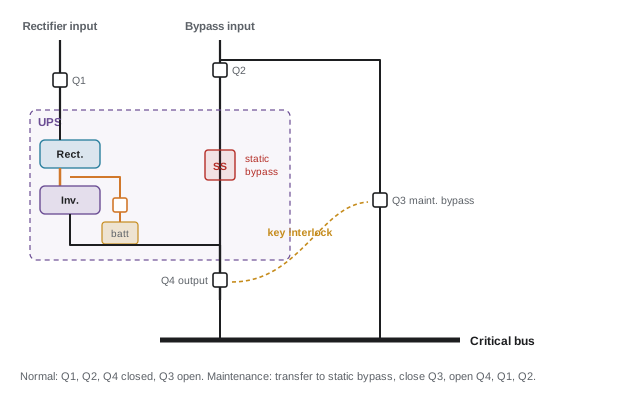
The static bypass is a solid-state switch (back-to-back thyristors) that connects the load directly to a bypass supply in under a few milliseconds if the inverter fails or is overloaded. Transfer is seamless only if the inverter is synchronized to the bypass, which it does continuously whenever the bypass is within limits. The bypass can be fed from the same source as the rectifier (single feed) or from a separate source (dual feed), which keeps the bypass available if the rectifier input breaker trips.
The maintenance bypass is a set of external breakers that route power around the whole UPS so that it can be isolated, de-energized and serviced while the load stays on (raw) utility or generator power. It must be interlocked, with key interlocks or electrically operated breakers, so that operators cannot parallel the inverter output with an unsynchronized source or open the wrong breaker. Many outages in the industry's incident reports occurred during maintenance bypass switching, which is why it is a carefully scripted procedure.
Modular and parallel UPS systems
Large UPS capacity is built either from big monolithic modules (500 kVA to 1.6 MVA) paralleled on a common output bus, or from frame-based modular systems in which 25 to 250 kW power modules slide into a cabinet. Modular systems allow capacity to grow with the IT load and offer internal N+1 redundancy: a 600 kW frame with seven 100 kW modules can lose one and still carry 600 kW. They also allow failed modules to be swapped without shutting down. Paralleled UPSs share load through communication between modules and must be synchronized to each other and to the bypass.
Worked problem
Modular redundancy and efficiency
A modular UPS frame holds up to ten 100 kW modules. The load is 520 kW, and the operator wants N+1 redundancy. How many modules must be installed, and what is the load per module? If the UPS efficiency is 96.5% at 75% module load but 95.0% at 50%, what does the module count mean for efficiency?
Show solution
- N modules to carry the load: \(\lceil 520/100 \rceil = 6\). N+1 = 7 modules.
- Load per module with all seven running: \(520/7 = 74\) kW, 74% loading.
- If the operator installed all ten modules, the load per module would fall to 52%, and efficiency would drop toward 95.0%.
Answer: Seven modules at 74% each, which also sits near the UPS's best efficiency. Many modular UPSs can put surplus modules to sleep automatically, so that the running modules stay well loaded.
UPS in the power chain
Large data centres place UPSs at the low-voltage level (480 V in the US, 600 V or 415 V in Canada, 400 V in many other countries) between the main switchboard and the PDUs, feeding critical loads through dedicated distribution. Mechanical loads that need to keep running through the generator start, such as chilled-water pumps, CRAH fans and controls, are often placed on a separate mechanical UPS so that cooling does not stop while the generators start. Medium-voltage UPSs (rotary or static at 4 to 15 kV) are used on some hyperscale campuses to reduce current and cable sizes.
Alternative approaches remove the central UPS altogether. Open Compute Project racks use a 48 V DC power shelf with built-in lithium-ion battery backup units inside each rack, eliminating one conversion stage and the central UPS room. Some hyperscalers place small batteries in each server. These designs trade the maintainability and monitoring of a central UPS for efficiency and simplicity at the rack.
How this course is organized
The twelve lessons follow the power path from the grid to the rack and then turn to the work of keeping it reliable:
- Lesson 1 (this lesson): UPS topologies, ratings and arrangements.
- Lesson 2: the utility supply and power quality, including sags, harmonics, ride-through and service arrangements.
- Lesson 3: UPS batteries, runtime, sizing, monitoring and battery room safety.
- Lesson 4: DC power and rack-level storage, from −48 V telecom plants and 380 V DC to high-voltage DC and battery backup units for AI racks.
- Lesson 5: generators, sizing for data centre loads, fuel and emissions.
- Lesson 6: battery energy storage systems, grid services and on-site generation such as gas engines and fuel cells.
- Lesson 7: transfer switches, paralleling switchgear and the sequence of operation in an outage.
- Lesson 8: protection and coordination when the source is a generator, UPS or battery rather than the utility.
- Lesson 9: redundancy architectures and availability calculations.
- Lesson 10: testing and commissioning, from factory tests to integrated systems testing.
- Lesson 11: operations and maintenance, procedures, monitoring and incident response.
- Lesson 12: a design project combining all of these for a mixed AI and conventional data hall.
Common mistakes
MistakeUsing a standby or line-interactive UPS for critical data centre loads.
InsteadUse double-conversion (VFI) or equivalent rotary systems so that input disturbances never reach the load.
MistakeChecking only the kVA rating of a UPS.
InsteadCheck both kVA and kW; with a 0.9 PF rating the kW limit is often reached first.
MistakeRunning UPS modules at very light load "for safety".
InsteadLight load reduces efficiency; size and stage modules so that they run near 50 to 80%.
MistakeOperating the maintenance bypass without a script and interlocks.
InsteadUse key or electrical interlocks and step-by-step procedures; switching errors are a leading cause of outages.
MistakeAssuming eco-mode is free efficiency.
InsteadIn eco-mode the load is exposed to input disturbances until transfer; evaluate site power quality and redundancy first.
Summary and key terms
- A UPS bridges the time from a utility disturbance until generators carry the load, and conditions power continuously.
- Sags and momentary interruptions are the most common disturbances; IT equipment rides through about 20 ms of interruption (ITIC curve).
- Standby (VFD), line-interactive (VI) and double-conversion (VFI) topologies differ in protection and efficiency; data centres use double-conversion.
- Eco-modes raise efficiency to about 99% at the cost of exposure to input disturbances.
- Rotary UPS, flywheels and DRUPS provide seconds of ride-through without batteries.
- Check both kVA and kW ratings; design loading is typically 80 to 90% maximum.
- IGBT rectifiers keep input harmonics low, which matters on generator power.
- The static bypass transfers on inverter failure or overload; the maintenance bypass, interlocked, allows the UPS to be isolated.
- Modular UPSs provide internal N+1 redundancy and scalability.
- UPS
- Uninterruptible power supply: equipment that supplies the load from stored energy when input power fails.
- Sag
- A short-duration drop in voltage to between 10 and 90% of nominal.
- ITIC curve
- The voltage tolerance envelope for IT equipment, formerly the CBEMA curve.
- Double conversion
- A topology in which all power passes through a rectifier and an inverter continuously.
- VFI
- Voltage and frequency independent: the IEC 62040-3 class for double-conversion UPSs.
- Line-interactive
- A topology with an inverter in parallel and voltage regulation by transformer taps.
- Eco-mode
- Operation with the load fed through the bypass and the inverter on standby.
- Static bypass
- A solid-state switch that transfers the load from the inverter to the bypass supply.
- Maintenance bypass
- External breakers that route power around the UPS for servicing.
- DRUPS
- Diesel rotary UPS, combining kinetic storage, a synchronous machine and a diesel engine.
- THDi
- Total harmonic distortion of current.
- Output power factor rating
- The ratio of a UPS's kW rating to its kVA rating.
- Modular UPS
- A UPS built from hot-swappable power modules in a common frame.
Practice problems
Work each problem on paper first, then reveal the answer to check.
According to the ITIC curve, how long should IT equipment ride through a complete loss of voltage?
Show answer
About 20 ms (roughly one cycle at 60 Hz).
Why is a double-conversion UPS classified VFI?
Show answer
Its output voltage and frequency are generated by the inverter, independent of input variations.
A 1.2 MW IT load runs through UPSs at 95.5% efficiency. What are the UPS losses?
Show answer
1200/0.955 − 1200 = 56.5 kW.
A UPS is rated 300 kVA at unity power factor. The load is 270 kW at 0.95 PF. What is its kVA loading?
Show answer
270/0.95 = 284 kVA, 95% of rating.
What are the main risks of eco-mode?
Show answer
The load is exposed to input disturbances until transfer, and transfer itself takes a few ms; harmonics from the load reach the supply.
Why are low input harmonics important on generator power?
Show answer
The generator's high source impedance converts harmonic currents into voltage distortion, which can disturb other loads and the generator controls.
What must be true for a seamless static bypass transfer?
Show answer
The inverter must be synchronized to the bypass source, which must be within voltage and frequency limits.
A 900 kW load is served by 250 kW modules with N+1 redundancy. How many modules, and at what loading?
Show answer
N = 4, N+1 = 5 modules at 900/5 = 180 kW, 72% each.
How long does a flywheel typically carry a full load, and why is that enough?
Show answer
10 to 30 s, enough for generators to start and accept load (often within 10 s).
Why is the maintenance bypass interlocked?
Show answer
To prevent paralleling unsynchronized sources or opening the wrong breaker, which could drop or damage the load.
Lesson quiz · 5 questions
Score 60% or more to complete this lesson.
Create a free account to save your progress, take quizzes and earn a certificate.